What are the functions of brake controls on railway vehicles? How are these functions defined, developed and tested? In the second part of our article series, engineers from Knorr-Bremse Budapest show how many different functions can be added to a rail brake control system, depending on the type of vehicle and customer requirements.
From design to software
Contact
Knorr-Bremse Vasúti Jármű Rendszerek Hungária Kft.
Helsinki út 105
1238
Magyarország - Hungary
info@knorr-bremse.com
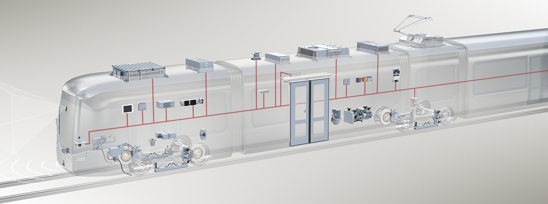
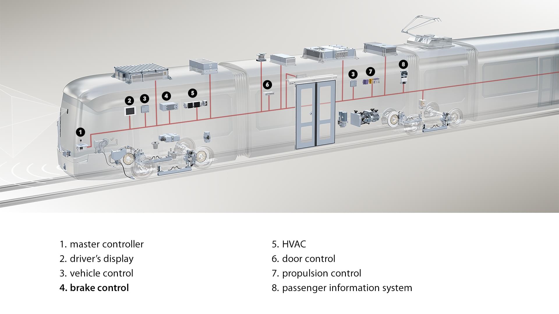
A customer project starts with a request for an offer from the customer – typically a rail vehicle manufacturer – which already shows what braking system(s) and functions are needed in the particular vehicle. At the concept level, the components of the mechanical/pneumatic system are selected, as well as the electronic units required to perform the specified tasks.
Once the offer is accepted and the order is placed, the work on the details can start. During the consultations with the customer, we specify exactly what connections the braking system will have with other vehicle systems, including mechanical, electrical and communication interfaces. The system engineer prepares a precise functional specification based on the customer's requirements, containing a description of the required tasks in a format that can be processed by the software developers and testers.
Let's see what these functions might be, varying from one vehicle type to another.
Take a brake with us
At Knorr-Bremse Budapest, every day we're working toward a safer and greener future. Take a "brake" with us. In a series of articles, we not only show how railway brake controllers and related features and systems work, but we also provide behind-the-scenes insights. Our engineers themselves tell us how development and testing takes place, how the various components are put together into a complete whole by the end of the process - things which ensure the passenger only feels that the vehicle is coming to a stop in the exact place and way in which it is supposed to.
Slide protection
Protection against wheel slide (Wheel Slide Protection – WSP) is perhaps the most basic feature of electronic brake controls that can be found in all vehicles. It has two main tasks:
- to ensure stable braking with the shortest possible stopping distance, even in poor track conditions,
- to prevent the wheel from "flattening" – as sliding can cause a small flat area to form on the wheel surface, which can create destructive vibrations during travel and damage both the undercarriage and the track.
Its basic principle is similar to that of ABS in cars: if the wheels slide, the braking force is quickly reduced to regain adhesion and to allow the wheel to pick up the speed of the vehicle. It continuously detects the speed of each axle and intervenes if the speeds of the axles deviate from each other (Δv) or if the measured deceleration (dv/dt) is greater than the maximum deceleration allowed for the vehicle by design (dvref/dt).
The WSP module can be used not only for pneumatic or hydraulic brakes, but also to control external (e.g. electrodynamic) brakes, if the wheels slide under their braking force. Furthermore, it is also possible to reduce the driving torque in the event of wheel spin by issuing a command to the drive, or even to slow down the spinning axles by applying the friction brake.
Brake force calculation, brake force distribution
A vehicle usually has several independent braking systems, which typically can be the following:
- the braking force (electrodynamic or hydrodynamic) is exerted by the drive system,
- electronically controlled friction brakes,
- purely mechanically controlled friction brakes,
- other (e.g. magnetic track brakes, spring-applied parking brakes, etc.)
The function of the brake control unit is to coordinate these; to calculate the braking force corresponding to the deceleration requested by the driver and to distribute the braking force between the different braking systems and between the individual units (carriages).
The brake that is capable of energy regeneration always has top priority. Typically, in the case of an electric drive system, this is the so-called electrodynamic brake, where the traction motors act as a generator in braking mode and feed the kinetic energy back into the overhead network or to other energy consumers in the vehicle. The basic principle is that the total braking force acting on the vehicle when braking is primarily provided by the regenerative braking system up to the limit of its potential performance. If additional braking force is needed, it is supplemented by friction brakes until the vehicle reaches the desired deceleration.
The distribution of braking forces between electric and mechanical brakes also depends on the speed, as the torque of the electric brake decreases at higher speeds. As such, the friction brake has to supplement more in this speed range. At low speed (<10km/h), the electrodynamic brake can no longer apply torque, so the mechanical brake has to take over the full braking force before stopping (blending). This must be done in such a way that the deceleration of the vehicle remains constant and no jerking can be felt.
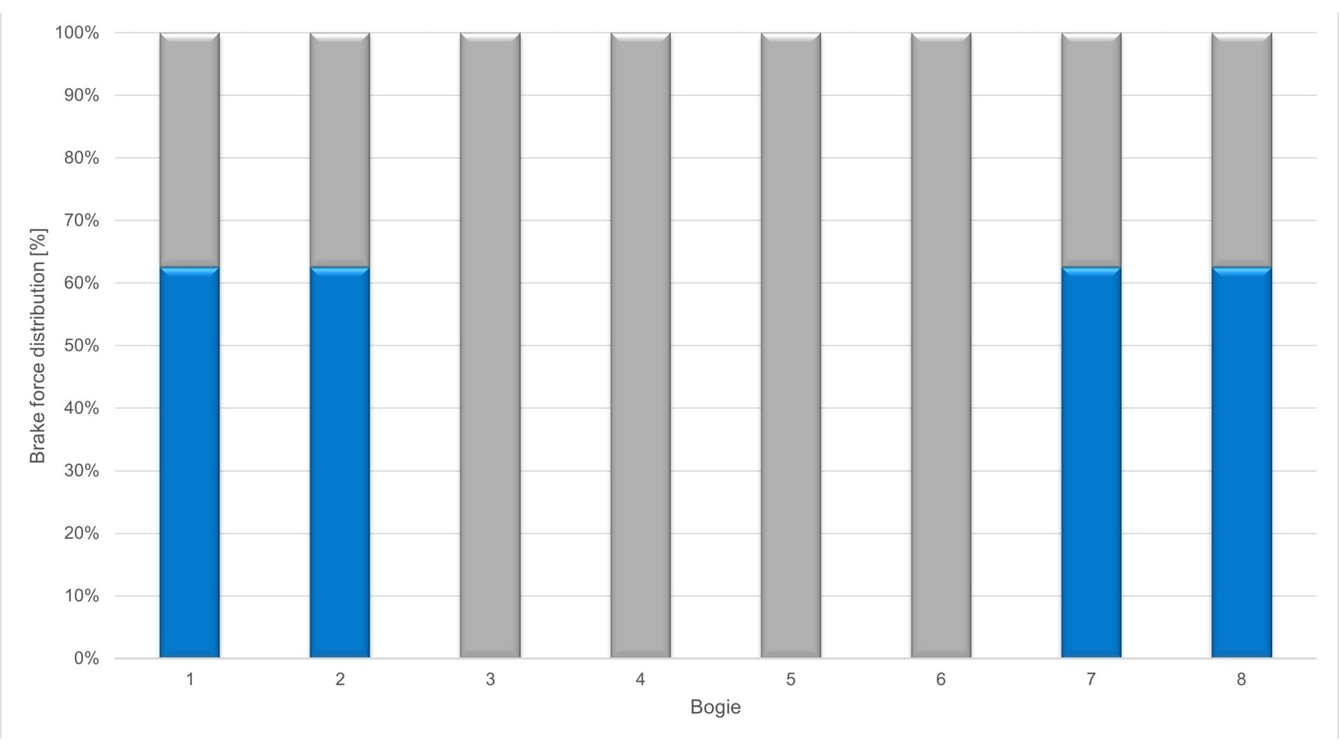
In multiple unit trains, braking force distribution between the carriages is a typical feature, which can work according to different algorithms, depending on the preferences of the vehicle manufacturer or the operator. For example, the principle may be that all carriages brake with the same deceleration, so that the minimum possible force is applied between the carriages. Another typical case is that all friction brakes brake with the same force (regardless of whether an axle is electrically braked as well), to ensure that the wear on the components is uniform. This way, maintenance can be planned more efficiently; the brakes on each carriage need to be renewed and replaced at the same time.
When calculating the braking force, the weight of the vehicle is always taken into account, in order to keep the braking force proportional to the actual load (F=m*a), so that the same deceleration is obtained at the same position of the brake lever.
Purely mechanically controlled brakes on modern trains are mainly used in auxiliary or emergency braking mode (and perhaps when towing a locomotive), when normal service brakes are not – or only partially – operational.
Communication
The brake control unit usually (also) communicates with the other control units of the vehicle via some kind of communication interface. This will be discussed in more detail in a future article.
Diagnostics, data storage
As the brakes are a safety-critical system, it is important that the controller continuously monitors the operation of the entire braking system and, if necessary, sends a fault signal to the vehicle controller. The faults are stored in the controller together with the related environmental variables, so that it acts as a "black box" and the cause of any fault can be investigated retrospectively.
The brake controller can continuously store any kind of data, so the recorded data can be read out not only in the case of a fault, but also in relation to any event.
Other functions
In addition to the above, there are many other functions that a brake control unit can perform, such as controlling air supply compressors, handling magnetic track brakes, performing brake tests, controlling parking brakes, and slide protection (sanding).
The development and testing process
At Knorr-Bremse, vehicle-specific applications are developed and tested in accordance with the relevant railway standards and often even more stringent internal specifications based on these standards. Of the software development methods, we use the so-called V-model, which means that each specification and development phase has a testing stage. In this way, the application software that will be used on the train will undergo at least 3 levels of testing (unit test, HW+SW integration test, overall system test), and this will be followed by the commissioning of the vehicle, where, together with the customer, the operator and the competent authorities, all the functions of the vehicle – including the braking system – will be tested, both in stationary and in running mode.
At Knorr-Bremse Budapest, we work every day for a safer and greener future. In our Brake with us series, we not only show you how rail brake controllers and related services and systems work, but also give you a glimpse behind the scenes. Our engineers explain personally how development and testing are carried out, how the various components combine to form a complete whole at the end of the process, and how the passengers only notice that the vehicle stops exactly where and how it needs to.