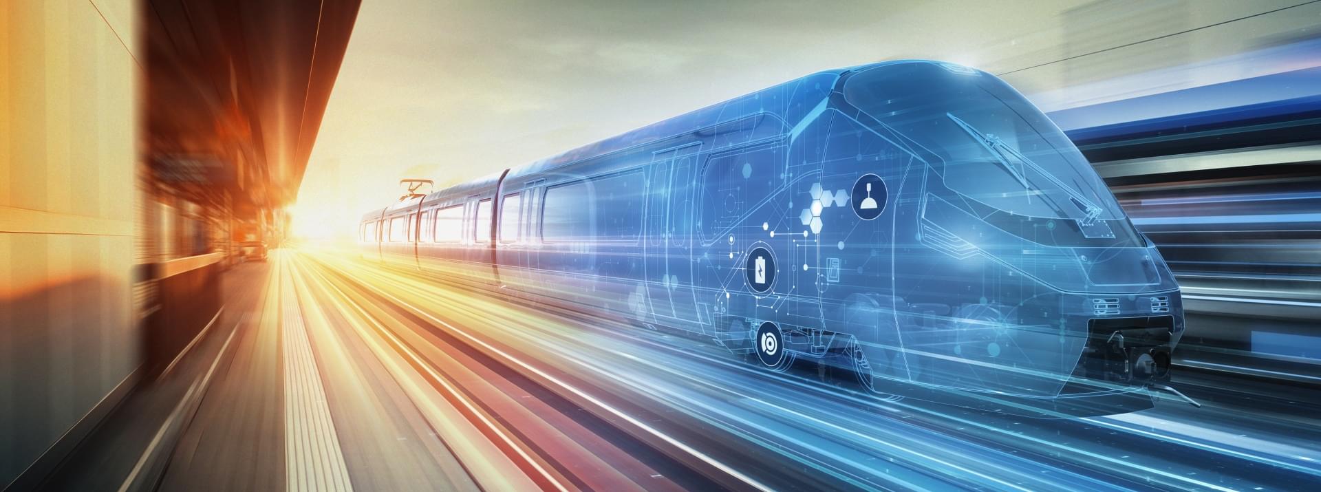
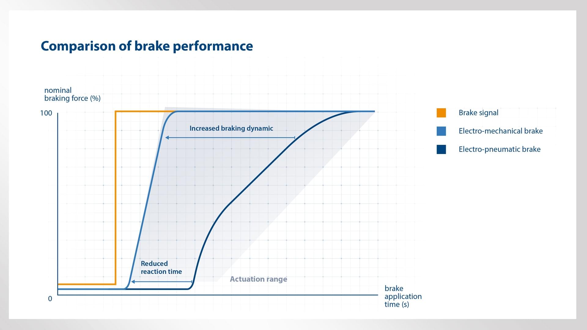
Although it has not yet made its way into mainline rail applications, the electro-mechanical brake (EM brake) is revolutionizing the way braking systems work in rail vehicles. In doing so, it is setting new standards of efficiency, reliability and performance. Unlike today’s pneumatic or hydraulic braking systems, the EM brake uses advanced brake-by-wire technology to generate and transmit braking signals and braking energy. Several mechanical and electrical components are directly integrated into the brake caliper, as are certain core braking functions. As a result of the improved braking dynamics and the corresponding improvement in the friction brake’s engage and release times, braking distances are reduced and track capacity is increased. The EM brake is a key enabler of the “airless train” – a train that dispenses with the usual complex system of compressors, brake reservoirs and pipes. Extensive field trials have already provided Knorr-Bremse with invaluable performance and operating data.
Contact
Carina Smid Marketing Rail
80809 München
Deutschland - Germany
carina.smid@knorr-bremse.com
Electricity as sole source of energy for braking system, signals and force
In conventional pneumatic or hydraulic braking systems, the medium of air (or hydraulic fluid) is used to produce and transmit braking signals and braking force. A complex system of compressors, brake reservoirs and pipes – in short, hydraulics – is installed in the vehicle for this purpose. The electro-mechanical brake, on the other hand, represents a technology whereby both braking signal and braking energy are generated and transmitted by electricity alone. Because pneumatic braking systems are proven, reliable and stable, rail vehicles will continue to use them for the foreseeable future. But because the technology is now very mature, any new developments throw up comparatively significant challenges. These make it difficult to meet the growing demands of vehicle manufacturers and operators for faster, more ambitious technological advances that will reduce vehicles’ weight and energy consumption while simultaneously improving their efficiency, availability and braking performance. Other demands include lower life cycle costs (LCCs) and lower total cost of ownership (TCO), to be achieved by developing low-maintenance systems with enhanced diagnostic capabilities embedded in a cutting-edge cybersecurity architecture. In terms of prospects, the “airless train” is regarded as a potential solution to these many demands. By using electric current as the energy vector and signal carrier, the EM brake represents a key factor in this equation.But even before “airless train” technology is ready for the market, brake-by-wire technology already offers significant advantages. Vehicle manufacturers benefit from weight and space savings, operators from improved braking performance, along with reduced LCCs and TCO. Not only does this provide opportunities to reduce train headway times and make better use of existing rail infrastructure, it also means that trains can be prepared and ready for operation even faster than before.
EM brake architecture and how it works in operation
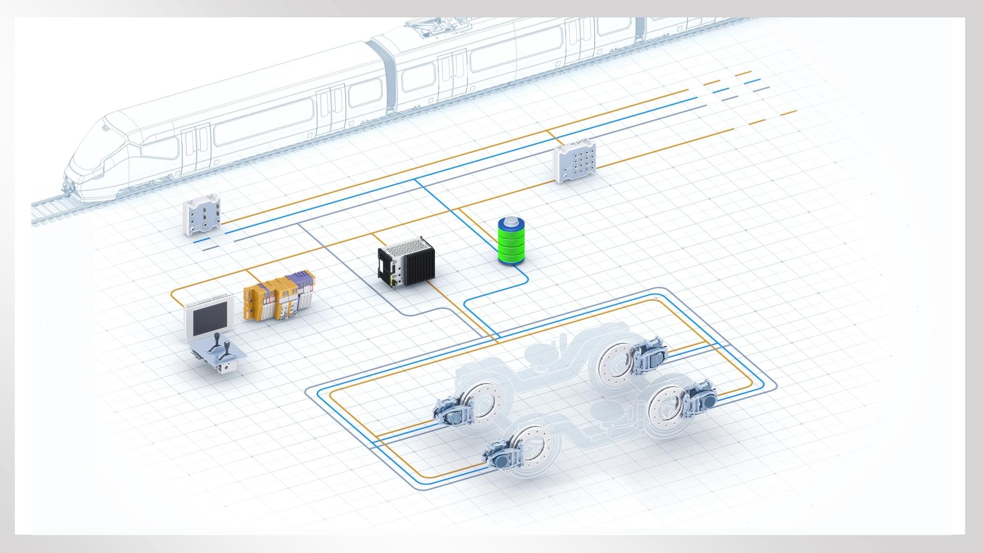
To implement precisely this kind of electric brake-by-wire technology, Knorr-Bremse has built an underlying architecture consisting of an electronic brake control unit (BCU), electro-mechanical brake calipers – each with its own electronics and dedicated electric motor – plus a built-in electrical energy management system. In the fully active system, control and feedback are managed via the vehicle’s CAN bus and hardwired cabling (such as “trainlines” for emergency and parking brakes). Control takes place at actuator level, with immediate availability at axle level. (Fig. 1)In the service brake, the target braking force requested by the vehicle – for example via the brake lever or Automatic Train Operation (ATO) environment – is input to the electronic brake control unit (BCU), which acts as a gateway to the vehicle control system. By taking into account, for example, the electrodynamic brake’s braking force, along with load correction and wheel slide protection, the BCU transmits the target braking force to the electro-mechanical brake calipers via the CAN bus. The calipers then apply the required braking force and send the relevant diagnostic data back to the vehicle via the BCU. An emergency braking command, on the other hand, is hardwired directly to all brake actuators in the train via the emergency brake loop. When an emergency braking command is issued, the target braking force, corrected for load and wheel slide, is independently adjusted at each brake caliper via the actuator’s internal electronics and electric motor, according to the train’s project-specific configuration. The associated diagnostic data is passed back to the vehicle via the CAN bus, BCU and hardwired link. Furthermore, the EM braking system is designed to ensure that the brakes are always under full control, both in normal operation and in the event of a fault. Even though the emergency brake has no mechanical or hydraulic fallback level, it fully complies with all relevant regulations and standards (e.g. SIL4).The parking brake is based on a similar architecture. The EM braking system passes the request to engage or release the brake to each of the train’s brake calipers. If a parking brake engage command is issued, the actuators regulate the target braking force independently of each other, similarly to the project-specific configuration. Once the target value has been attained, the parking brake’s braking force is mechanically locked for an unspecified period. This means that the vehicle is securely prevented from rolling away in any and all circumstances, even in an unpowered state. The parking brake is released by a signal transmitted over the corresponding trainline. The electrical energy required for braking is normally provided by the train, with the input voltage supplied to the electro-mechanical actuators via the dedicated energy management system. Because the train’s energy supply is monitored by the EM braking system’s internal electronics, the latter detects any failure or outage. In the event of an outage, the system automatically switches over to its own internal energy supply while sending a corresponding diagnostic report to the vehicle.Designed to comply with all TSI requirements and the very highest safety standards for braking functions, the electro-mechanical brake will meet all standards and cybersecurity requirements in force at the time of its market launch. The necessary measures will be implemented at both electronic BCU level and actuator level.
Flexible onboard arrangement without project-specific hardware
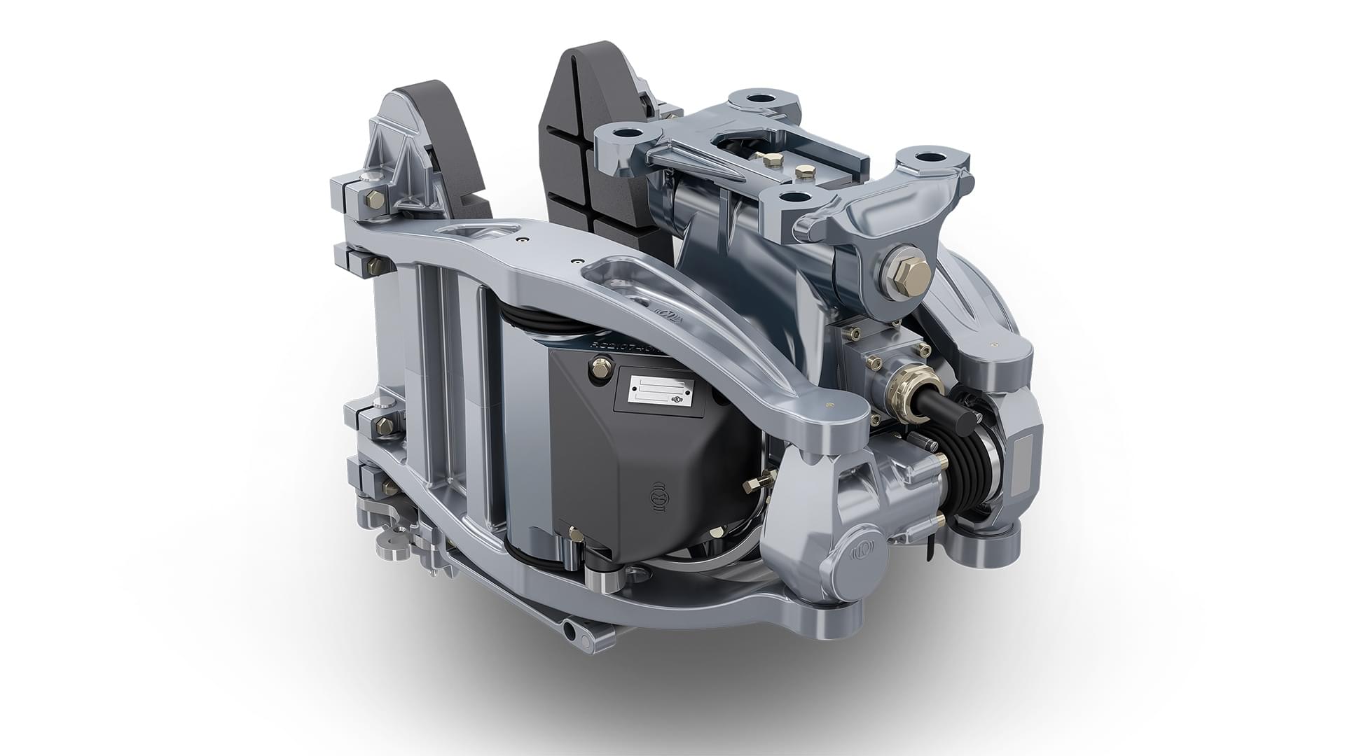
A system architecture that does not use air as the energy medium has numerous advantages for manufacturers and operators alike. First, when designing vehicles, the manufacturer benefits from the weight and space savings. And because no piping is required, the individual EM braking system components can be arranged with considerable flexibility. Preliminary studies show that realistically, depending on vehicle configuration, the weight of the braking system alone – before taking the elimination of pipework into account – can be reduced by up to 15 percent. The system is also easy to install, because Knorr-Bremse used the existing RZTXS brake caliper (a popular compact pneumatic caliper for wheel brake discs) as the basis for the EM brake caliper; the latter takes up the same amount of space and uses the same mechanical interfaces on current bogies.For operators, lean system architecture and weight savings initially pay off in the form of lower TCO; the same applies to the more efficient generation of braking force, because the comparatively inefficient transfer of energy via the medium of compressed air is no longer required. Similarly, the cost of additional hardware to meet special customer requirements no longer enters into the equation: developers can flexibly implement project specifications such as vehicle-specific clamping forces by adjusting software settings. This reduces time to market. Finally, the system’s support for “smart” diagnostics and monitoring of wear on brake pads and brake discs optimizes maintenance intervals (Fig. 2)
The improved performance that characterizes EM braking systems is not confined to braking dynamics alone; it also offers opportunities to optimize existing functions. The EM brake’s substantially faster response time, for example, shows significant potential for optimizing wheel slide protection designed for low-adhesion conditions. When trains are being prepared for operation, EM braking systems reduce setup times because compressors no longer need to bring a hydraulic air supply system up to operating pressure. Instead, the EM braking force is available immediately, as soon as the vehicle electronics are switched on. Similarly, the obligatory brake test can now be comprehensively revised: With the EM brake, today’s time-consuming, labor-intensive inspection process can be automated and optimized so that the train is fully operational even faster than before.
Current development status
Knorr-Bremse has successfully embedded the field testing of the EM brake in the European innovation program Europe’s Rail Joint Undertaking (ERJU)*. The project team is working on this key enabler of the “airless train” within the Flagship Area for a “sustainable and green rail system”.
Extensive field trials involving more than 200 braking maneuvers at speeds of up to 160 km/h have already yielded valuable operating data on both service braking and emergency braking maneuvers with wheel slide protection, as well as braking while crossing switches, and use of the parking brake. The next stage will involve testing a complete trainset equipped with an EM braking system. Starting in 2026, the technology could cover the entire mainline segment.


Author: Josef Baier
Litrature:
* Funded by the European Union. The views and opinions expressed in this article are, however, solely those of the author and do not necessarily reflect those of the European Union or ERJU. Neither the European Union nor ERJU may be held responsible for them.
** The project is supported by the Europe’s Rail Joint Undertaking (ERJU) and its members.
Print Version
Printed Version