Higher train frequencies: Innovative wheel slide protection for improved utilization of rail infrastructure
In Knorr-Bremse’s Reproducible Braking Distance (RBD) approach, three integrated braking technologies combine to significantly reduce braking distance variation and spread: an innovative deceleration control system, a train-wide adhesion management system capable of adapting to different situations, and enhanced wheel slide protection with optimized adhesion utilization. In adverse rail conditions, the available maximum wheel-rail adhesion values can lie within a wheel slip range that is not systematically exploited by conventional wheel slide protection systems. The new wheel slide protection system addresses this problem. At its core is the new WSPA-3 wheel slide protection algorithm, which switches to a newly implemented alternative control range for extremely low adhesion conditions whenever this allows a greater braking force to be achieved compared to the standard control range. As a result, the algorithm can enable braking force transmission in rail conditions under which, until now, almost no braking force was transmitted.
Contact
80809 München
Deutschland - Germany
carina.smid@knorr-bremse.com

Introduction - Major improvement to the wheel slide protection system
Wheel slide protection systems in rail vehicles work in a similar way to the ABS anti-lock braking system in motor vehicles by preventing the axle from locking if the adhesion conditions at the wheel/rail contact suddenly deteriorate while braking. This can happen, for instance, when the track is wet, if there are leaves on the line or in high humidity. Wheel damage, such as flat spots, can be a direct result of axles locking in this way. Rather than simply protecting the wheels, however, wheel slide protection systems are designed to make optimum use of the adhesion currently available at the wheel/rail contact in order to minimize braking distance.
Longer braking distances have a significant impact on the overall rail system, as they are factored in when calculating the minimum headway between two trains, along with the necessary safety margins. Conversely, if rail vehicles are to brake more reliably under all ambient conditions, this helps to shorten headways and thus utilize the existing rail infrastructure more effectively.
In view of this, Knorr-Bremse is aiming to significantly reduce braking distance variation and spread with its Reproducible Braking Distance (RBD) project. This involves an innovative deceleration control system, a train-wide adhesion management system and adaptive wheel slide protection control with optimized adhesion utilization working together as an integrated whole for the first time.
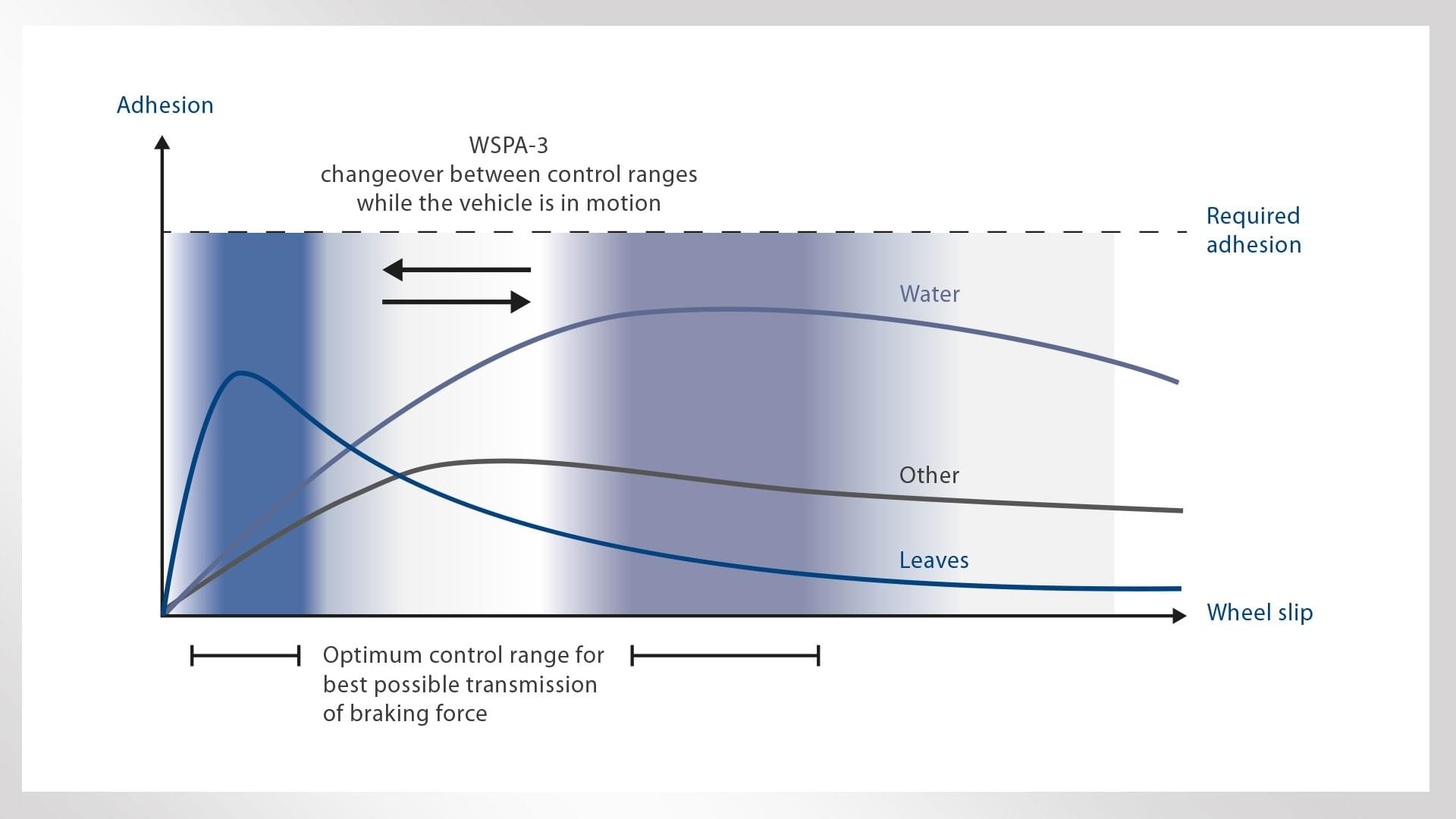
Conventional wheel slide protection systems are basically optimized for low adhesion conditions with maximum values in the UIC control range above ten percent slippage (macro-slip range), i.e. the range where vehicle speed exceeds wheel speed by ten percent. Targeted adjustment of the wheel slide protection control to adhesion conditions with a distinct peak in the micro-slip range (below five percent) has not been an explicit requirement of the applicable standards (UIC 541-05, EN 15595, NR - GM/GN2695) in the past.
This is where the new WSPA-3 wheel slide protection algorithm comes into play. In situations where the micro-slip range offers significant benefits in terms of braking force, the controller switches from macro-slip mode to the newly implemented Low Adhesion Mode (LADM) for micro-slip (Figure 1). If the conditions then change back again, the controller will revert to the mode for the standard control range with over ten percent wheel slip. In this way, the WSPA-3 algorithm enables greater braking force to be transmitted on extremely slippery tracks with adhesion values peaking in the micro-slip range, thereby exceeding the requirements stipulated in the standards. In order to determine the level of adhesion at the wheel/rail contact and thereby change between the operating modes at the right point, WSPA-3 comes complete with an adhesion monitor that analyzes the total braking force at each wheelset. (Implementation of the WSPA-3 algorithm requires it to govern all of the braking systems acting at a given wheelset.)
Summary
In Knorr-Bremse’s Reproducible Braking Distance (RBD) approach, three integrated braking technologies combine to significantly reduce braking distance variation and spread: an innovative deceleration control system, a train-wide adhesion management system capable of adapting to different situations, and enhanced wheel slide protection with optimized adhesion utilization. In adverse rail conditions, the available maximum wheel-rail adhesion values can lie within a wheel slip range that is not systematically exploited by conventional wheel slide protection systems. The new wheel slide protection system addresses this problem. At its core is the new WSPA-3 wheel slide protection algorithm, which switches to a newly implemented alternative control range for extremely low adhesion conditions whenever this allows a greater braking force to be achieved compared to the standard control range. As a result, the algorithm can enable braking force transmission in rail conditions under which, until now, almost no braking force was transmitted.

Operating principle of the new WSPA-3 wheel slide protection algorithm
If a wheelset begins to slide during braking, the WSPA-3 algorithm starts to calculate the braking forces that can be attained between wheel and rail in both the micro- and macro-slip ranges. These forces are proportional to the available adhesion and are averaged for the system as a whole. Averaging the forces provides a meaningful basis for comparing the maximum adhesion values for micro- and macro-slip and ensures they are not distorted by brief variations or isolated adhesion peaks.
Adhesion is calculated on the basis of the brake cylinder pressures, taking into account the braking forces exerted by other external braking systems, such as an electrodynamic brake, as well as wheelset acceleration and specific vehicle parameters. The braking force values are read via an interface to the vehicle control system. If the comparison of adhesion values for micro- and macro-slip indicates a significant gain in the micro-slip range, the algorithm will switch from macro-slip mode to the Low Adhesion Mode (LADM) designed for micro-slip.
After switching mode, all axles will initially be controlled in the micro-slip range. As both the adhesion conditions between wheel and rail and the relative values for maximum micro-slip and macro-slip adhesion can change rapidly, however, the control mode is subject to ongoing verification by WSPA-3. The test algorithm developed for this purpose keeps reactivating macro-slip mode for at least one wheelset, while the adhesion monitor gathers data in order to reevaluate the adhesion conditions. If macro-slip control of the test axle proves to be more effective, it will remain in this mode.
Repeating the adhesion test at further wheelsets enables multiple axles to revert to macro-slip control. This hybrid form of axle control in both the micro- and macro-slip range allows continuous adaptation to the prevailing adhesion conditions.
In addition to this, the adhesion monitor constantly performs a background comparison of the braking force averages for the two slip ranges. If the braking forces at the macro-slip axles result in more effective vehicle deceleration, the system will switch back to macro-slip mode. After reverting to this mode the braking forces will continue to be monitored, so the cycle may start over.

In-vehicle testing: braking distance shortened by around ten percent
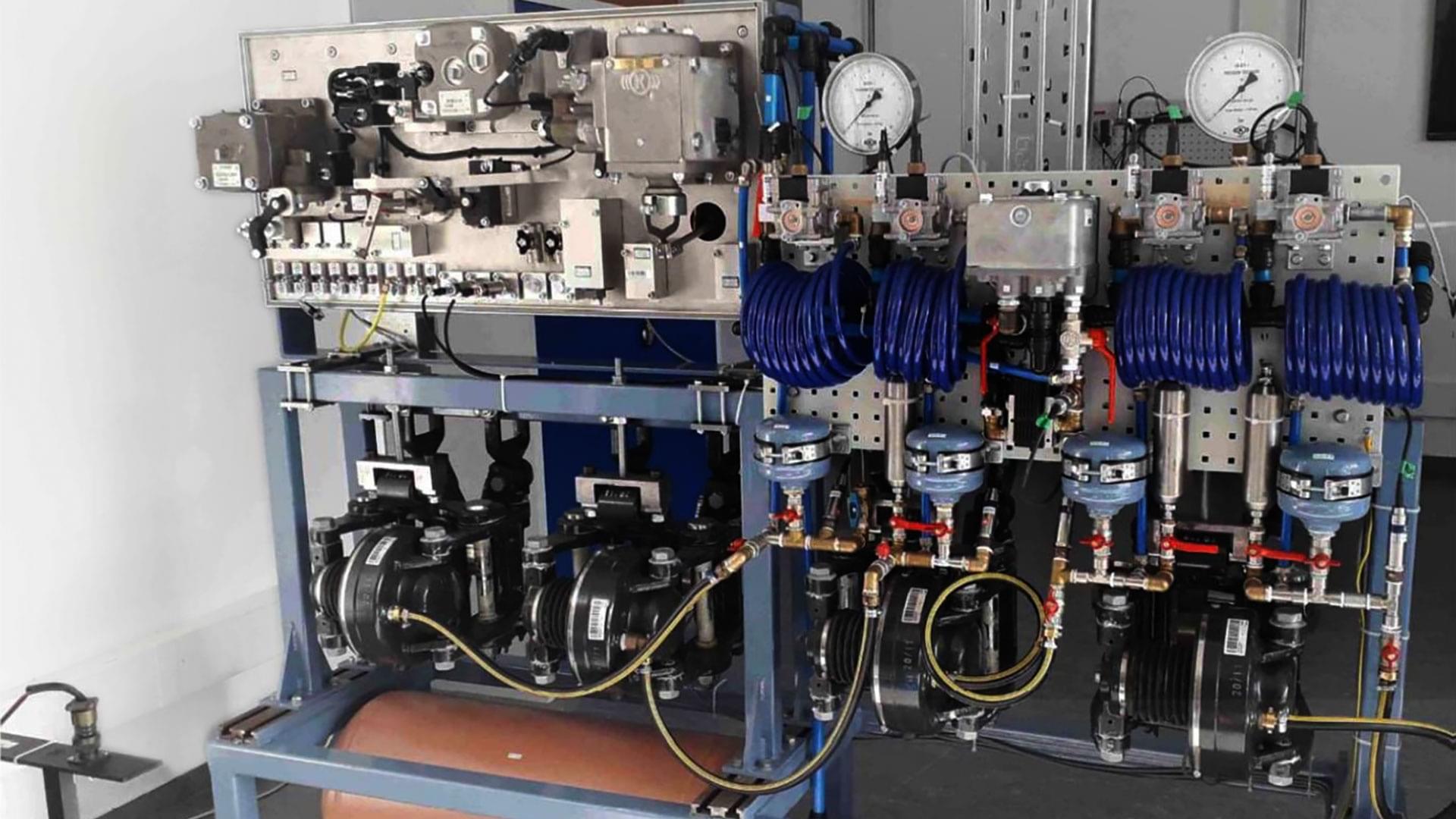
Prior to in-vehicle testing of WSPA-3, the algorithm was optimized and validated on the wheel slide protection system test rig (Figure 2). The test rig meets the requirements of the relevant standards and comprises the wheel slide protection control unit, along with the entire pneumatics for a passenger car complete with brake actuators and wheel speed measurement devices using real-world components. The vehicle and wheel/rail contact are replicated using a complex simulation model. A wide variety of configurable system states with static and dynamic adhesion curves means that wheel slide protection systems can undergo extensive optimization and testing before being installed in an actual vehicle.
As part of the UIC approval process for the MGS3 wheel slide protection system for passenger cars, which has the WSPA-3 algorithm at its core, in-vehicle testing was conducted on tracks prepared in different ways. As well as the stipulated braking tests on tracks sprayed with a soap solution, braking distance measurements were also performed at extremely low wheel/rail adhesion values. In order to achieve such values, a section of line approximately 1,000 meters long was prepared with paper tape then sprayed with water before testing commenced.
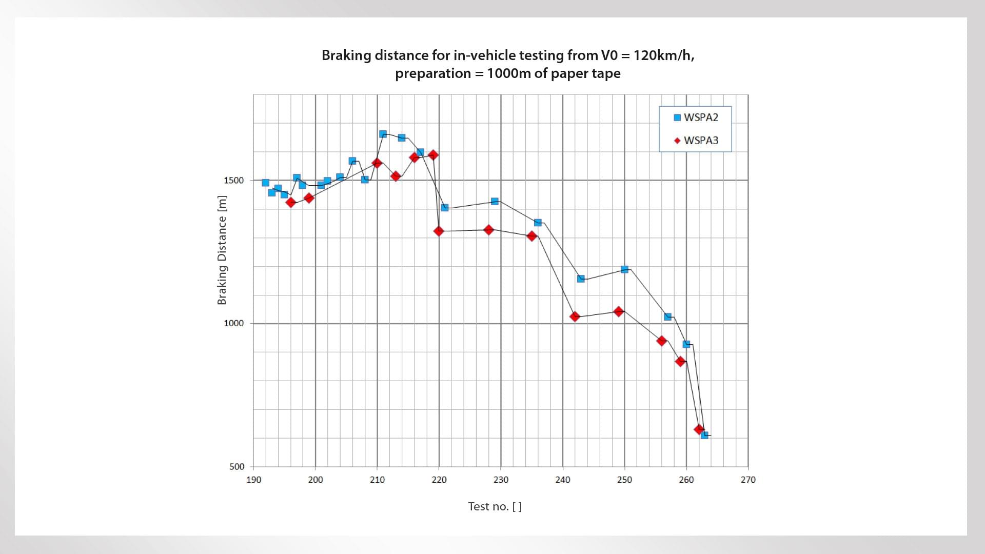
These extreme track conditions subsequently provided the basis for comparative tests of the adaptive wheel slide protection control (WSPA-3) and a conventional control concept (WSPA-2). Control was switched from WSPA-3 to WSPA-2 between two consecutive braking tests. The benefit of the new adaptive control concept is clearly illustrated by the summary of braking distance results for the comparative tests (Figure 3).

Test analysis and outlook
Adhesion at the start of the test series (T192 – T210) was extremely low (<0.015) and the adhesion/slip curve does not have a distinct peak (see Figure 1, adhesion type ‘other’). Consequently, the braking distances with WSPA-2 and WSPA-3 are approximately the same for these test runs, as was to be expected.
During subsequent testing, adhesion was gradually modified after each pair of comparative test runs with WSPA-2 and WSPA-3 and shifted towards an adhesion/slip curve peaking in the micro-slip range (see Figure 1, adhesion type ‘leaves’). The results from test 210 onwards show that the WSPA-3 algorithm offers a clear advantage in such adhesion conditions, shortening the braking distance by around ten percent.
As testing progressed, repeated crossing of the same stretch of track and appropriate cleaning after each pair of comparative test runs had the effect of increasing adhesion on the prepared section of line and altering the adhesion qualities. As a result, braking distances became progressively shorter. These changes in adhesion meant that as the test series drew to an end (approx. T262) the adhesion type equated to ‘water’ (see Figure 1) with maximum adhesion in the macro-slip range. Predictably, at this point the braking distances with WSPA-2 and WSPA-3 were approximately the same again. Following the test runs, the robustness of WSPA-3 was verified by a field trial in six passenger cars that lasted over a year.
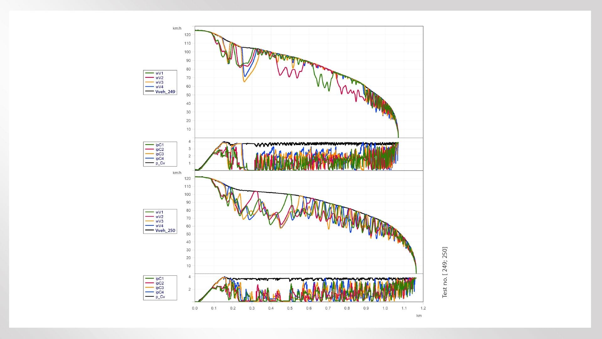
The two test runs shown in Figure 4 were performed immediately after one another at exactly the same braking point in order to ensure comparable adhesion conditions. The switch to LADM upon reaching the prepared section of track and the resulting changeover to the micro-slip range for axle control are clearly visible in test 249 (WSPA-3). In test 250 (WSPA-2), on the other hand, the system intentionally remains in the macro-slip control range throughout.
The WSPA-3 wheel slide protection algorithm has now been deployed in the control units of the latest generation of brake control systems from Knorr-Bremse, where it is helping to keep braking distances short in all adhesion conditions. Within the context of the RBD approach, enhanced wheel slide protection control offers additional benefits, particularly with a view to automatic train operation (ATO). The next step in this project is to lay further foundations for reducing the headway between trains without compromising on safety by ensuring predictable braking distance variation.

Authors: Reinhold Mayer, Thomas Rasel

