
Deceleration-controlled vehicle enables a more stable braking behavior in all speeds.
Optimal braking process reproducibility is a key design objective for modern braking systems. The new Deceleration Control (DCC) function takes an important step in this direction by largely decoupling the train’s actual deceleration from variable operating conditions and the tolerances of the brake and bogie equipment. This enables more stable braking behavior, making it possible to stop the train within a precise braking distance from any speed and for all brake types, regardless of variability in the coefficient of friction between brake pad and brake disc. After more than two years of development and extensive testing on "Impuls" platform vehicles, Knorr-Bremse Rail Vehicle Systems (SfS) and Polish manufacturer NEWAG have received approval from the Polish railway authority Urząd Transportu Kolejowego (UTK) for a three-car regional multiple unit with the new control function. The next step is a one-year field trial on regular passenger service.
Contact
Carina Smid Marketing Rail
80809 München
Deutschland - Germany
carina.smid@knorr-bremse.com
Introduction
If a rail vehicle has to brake suddenly or perform an emergency stop, the braking system generates a consistent, load-dependent emergency brake pressure on all the wheelsets. Under ideal conditions, this consistent pressure would always ensure similarly consistent deceleration and braking distances, since exactly the same braking force is applied to the wheels.
In the real world, however, vehicles do not operate under ideal conditions. Even in adequate adhesion conditions, the actual deceleration values and resulting braking distances have significant tolerances. This is mainly due to variability in the coefficient of friction of the chosen brake pad and brake disc friction pairing. The coefficient of friction is mostly determined by variations in brake disc temperature linked to the driving profile prior to the braking event. The temperature of the discs is determined by the energy input, which is itself influenced chiefly by the speed at which the vehicle is traveling when braking is initiated. Conditioning effects can also have an impact on subsequent braking maneuvers. In addition, the coefficient of friction is affected by external parameters such as temperature and humidity.
Other braking system tolerances such as brake actuator efficiency and imprecise wheel diameter values due to wear also directly affect the braking force applied to the wheelsets. The combined effect of these numerous variables can translate into substantial braking distance variation.
Certain tolerances are factored into the design of braking systems to make sure that the train always comes to a halt within the maximum permitted emergency braking distance, even under the most adverse conditions. The same applies to failures, for example the failure of an entire bogie. Most braking systems are more highly specified than they need to be to cope with even the most adverse scenarios.
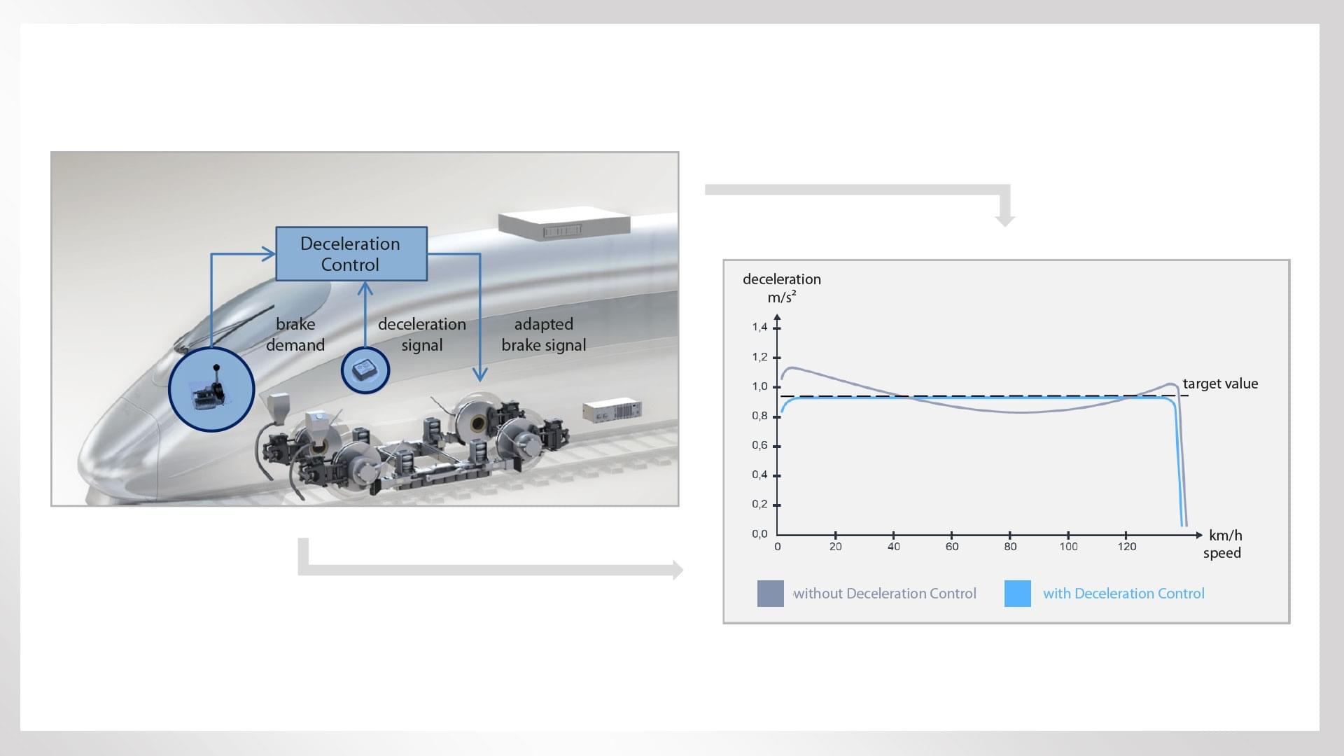
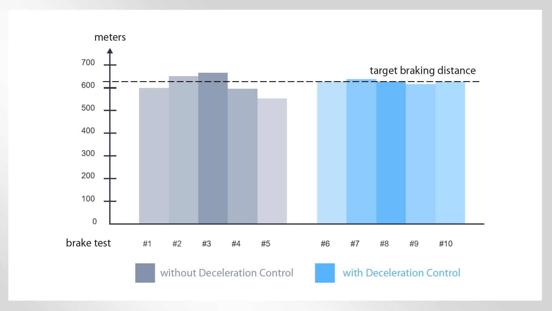
The influence of the system tolerances described above can be reduced by a Deceleration Control function that responds immediately to any discrepancy between current deceleration and the desired brake demand value (Figure 1). This significantly reduces braking distance variation and prevents the train from overshooting the braking distance due to braking equipment tolerances and wheel diameter variation (Figure 2). The ability to stop within the specified braking distance is thus largely decoupled from brake pad friction behavior.
Summary
Optimal braking process reproducibility is a key design objective for modern braking systems. The new Deceleration Control (DCC) function takes an important step in this direction by largely decoupling the train’s actual deceleration from variable operating conditions and the tolerances of the brake and bogie equipment. This enables more stable braking behavior, making it possible to stop the train within a precise braking distance from any speed and for all brake types, regardless of variability in the coefficient of friction between brake pad and brake disc. After more than two years of development and extensive testing on "Impuls" platform vehicles, Knorr-Bremse Rail Vehicle Systems (SfS) and Polish manufacturer NEWAG have received approval from the Polish railway authority Urząd Transportu Kolejowego (UTK) for a three-car regional multiple unit with the new control function. The next step is a one-year field trial on regular passenger service.
The Deceleration Control (DCC) function
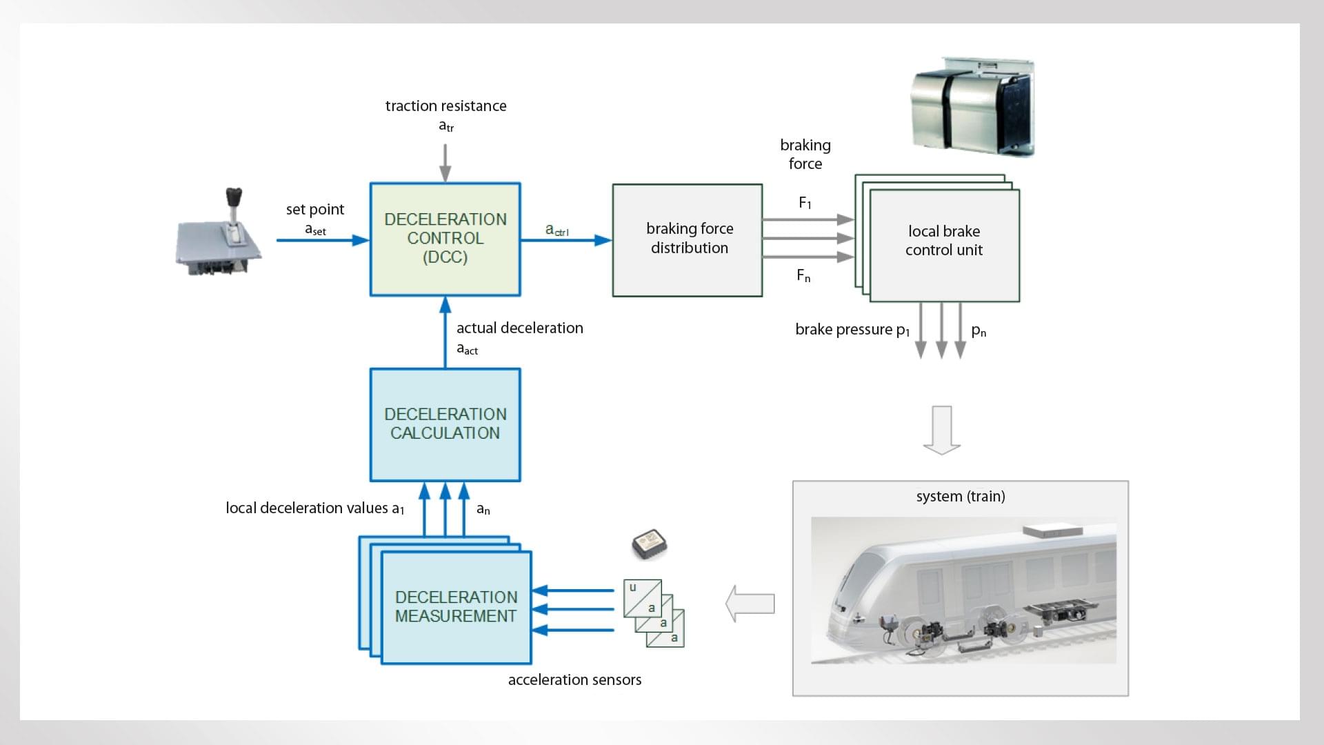
Each car in the train is fitted with a deceleration sensor that constantly measures actual longitudinal acceleration. The measurements are sent to the central brake control unit via the train bus, supplying the Deceleration Control (DCC) system integrated into the brake control path with real-time information about the actual effect of the applied braking force (Figure 3). DCC constantly minimizes the difference between the train’s measured deceleration and the set point for the train’s required degree of deceleration.
The Deceleration Control function is deployed in both the service and the emergency brakes and affects all the active pneumatic and electrodynamic brakes of both brake types. The system applies the appropriate brake pressure to the individual bogies or axles based on the required degree of deceleration, taking into account current speed, outside conditions, track gradient, vehicle and car parameters such as load, and the performance of the friction material. This means that actual deceleration is to a large extent decoupled from variability in vehicle operating conditions and tolerances. Maximum braking distance variation is also reduced significantly for the emergency brake function.
Equipping a test train’s service brake with the Deceleration Control function
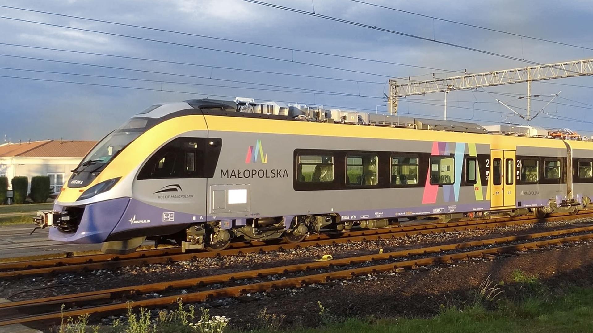
Up to this point, the function had been designed and simulated in a virtual environment. The next step in its development was therefore to test it on a real vehicle. Polish manufacturer NEWAG provided an almost completely new Impuls 31WE electric multiple unit, a four-car regional train (Bo‘ 2‘ 2‘ 2‘ Bo‘) with a top speed of 160 km/h (Figure 4). Each bogie is fitted with an EP Compact pneumatic brake control unit. The associated electronic control equipment is located in each half of the train.
In summer 2016, the train was modified for test runs with the new Deceleration Control function. For the test implementation, an extra prototype control unit for the Deceleration Control function was integrated alongside the existing electronic brake control units. Four acceleration sensors distributed along the train were connected to this module in order to measure the vehicle’s longitudinal deceleration. The driver’s brake set point was adjusted in line with the measured actual deceleration and transmitted to the brake control units.
The setup allowed for operation with or without Deceleration Control in order to enable a direct comparison between braking behavior in “DCC on” and “DCC off” modes during the subsequent testing. Since modifications to the installed pneumatics were not permitted, Deceleration Control was only implemented for the service brake on this first test train. The train’s test installation was supplemented by a number of additional speed and acceleration sensors for carrying out reference measurements during the trial.
Initial test runs on the IK test track near Żmigród
Testing began at the end of August 2016 on a test track belonging to the Instytut Kolejnictwa (IK) near Żmigród. Among other things, the Polish Ministry of Transport, Construction and Maritime Economy’s IK Railway Research Institute is responsible for interoperability matters pertaining to rail transportation in Poland. The test runs tested braking with different loads and friction materials (the original JURID 878 brake pads and alternative Propad P16 brake pads).
In the interests of comparability, braking was applied with the same brake demand for a range of initial speeds until the train came to a stop. The tests differentiated between Deceleration Control “on” and “off” modes and also switched between exclusively electropneumatic braking and blending mode with an electrodynamic brake. Subsequent brake tests were carried out with different controller parameters and for specific equipment failure scenarios.
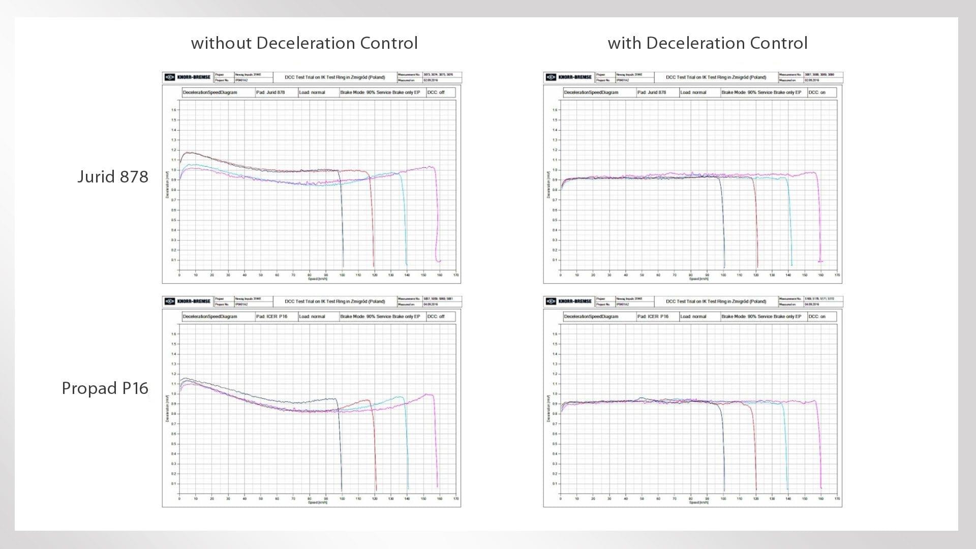
280 test circuits were completed (approximately 2,200 kilometers in total) and 203 braking maneuvers were measured. The results were unequivocal. The characteristic
“bump” in the braking deceleration curve was completely flattened out, and there was a marked reduction in braking distance variation from the same initial speed. The measurements plotted in Figure 5 illustrate the effect of the DCC function with the service brake activated in electropneumatic only mode at 90% brake demand. Without Deceleration Control, the deceleration curves and thus the braking distances are strongly influenced by initial speed and coefficient of friction behavior. With DCC activated, the specified set point is regulated with an adequate degree of precision, resulting in excellent braking distance reproducibility. This also results in even adhesion utilization in all ranges and at all speeds. DCC is particularly successful at levelling off the increase that typically occurs with many friction materials at low speeds, with the resultant positive effect on braking performance.
Equipping and homologation of a multiple unit with DCC for operational deployment
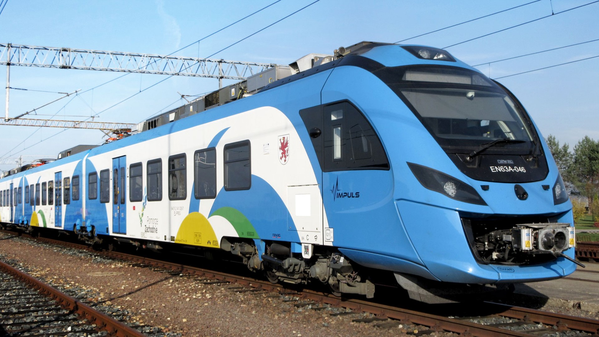
Following the positive prototype test results, the logical next step in the system’s development was to equip the emergency brake too with this functionality and test the system in a regular operational setting. However, this involved far more extensive adjustments to the pneumatic and electronic brake control units. This new, major modification of the entire braking system was carried out on a three-car NEWAG Impuls 36WEa multiple unit (Figure 6) with a top speed of 160km/h.
As well as directly integrating the Deceleration Control function with the train’s original brake control electronics, all the pneumatic EP Compact units were replaced with new, modified units that also enable Deceleration Control during emergency braking. NEWAG provided invaluable assistance with the modification, which was carried out at the Nowy Sącz production facility. The Polish company was also responsible for the vehicle’s homologation.
An extensive testing program was initiated in November 2018 to ensure that the vehicle was as well prepared as possible for homologation. As well as the test runs for the commissioning and optimization of the new control function, the program also included test runs mimicking the UIC/TSI homologation process.
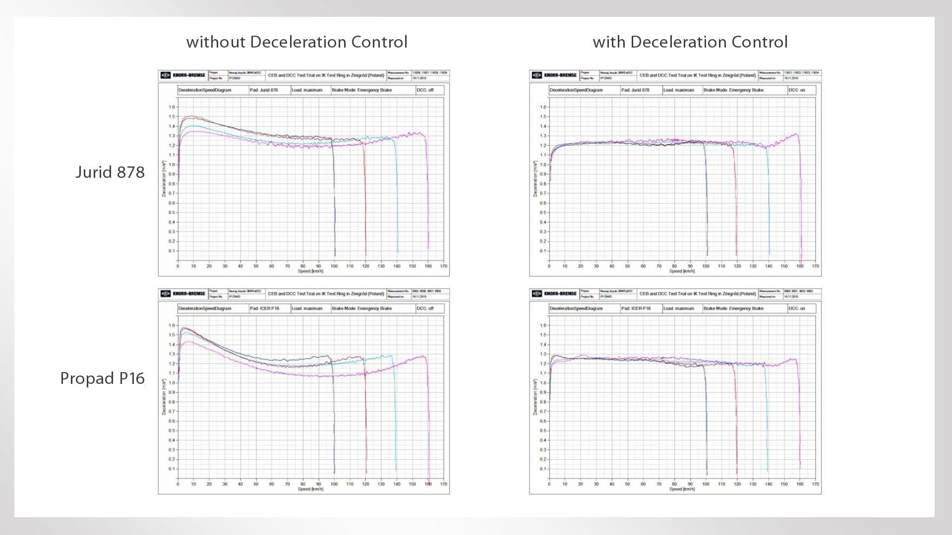
The testing program comprised 826 test circuits (6,210 km). Test runs were carried out with empty vehicles and vehicles with normal and maximum loads, and here too with either JURID 878 or Propad P16 brake pads. Measurements were carried out under different conditions for both the service and emergency brakes, while various failure scenarios were also simulated. Figure 7 is similar to the graphs for the 2016 tests. It illustrates the deceleration curves of a loaded vehicle – this time for emergency braking – from different initial speeds and with two different friction materials. The trend identified in the earlier tests was confirmed – when electronic Deceleration Control was activated, braking distance variation was reduced by up to 85% for the emergency brake, too.
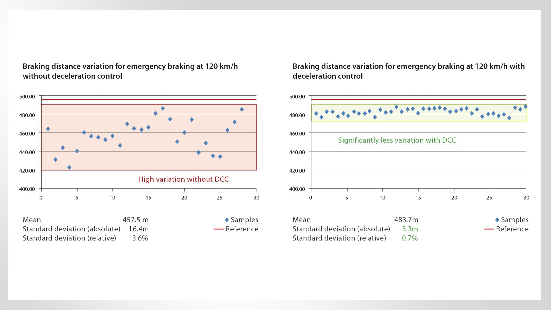
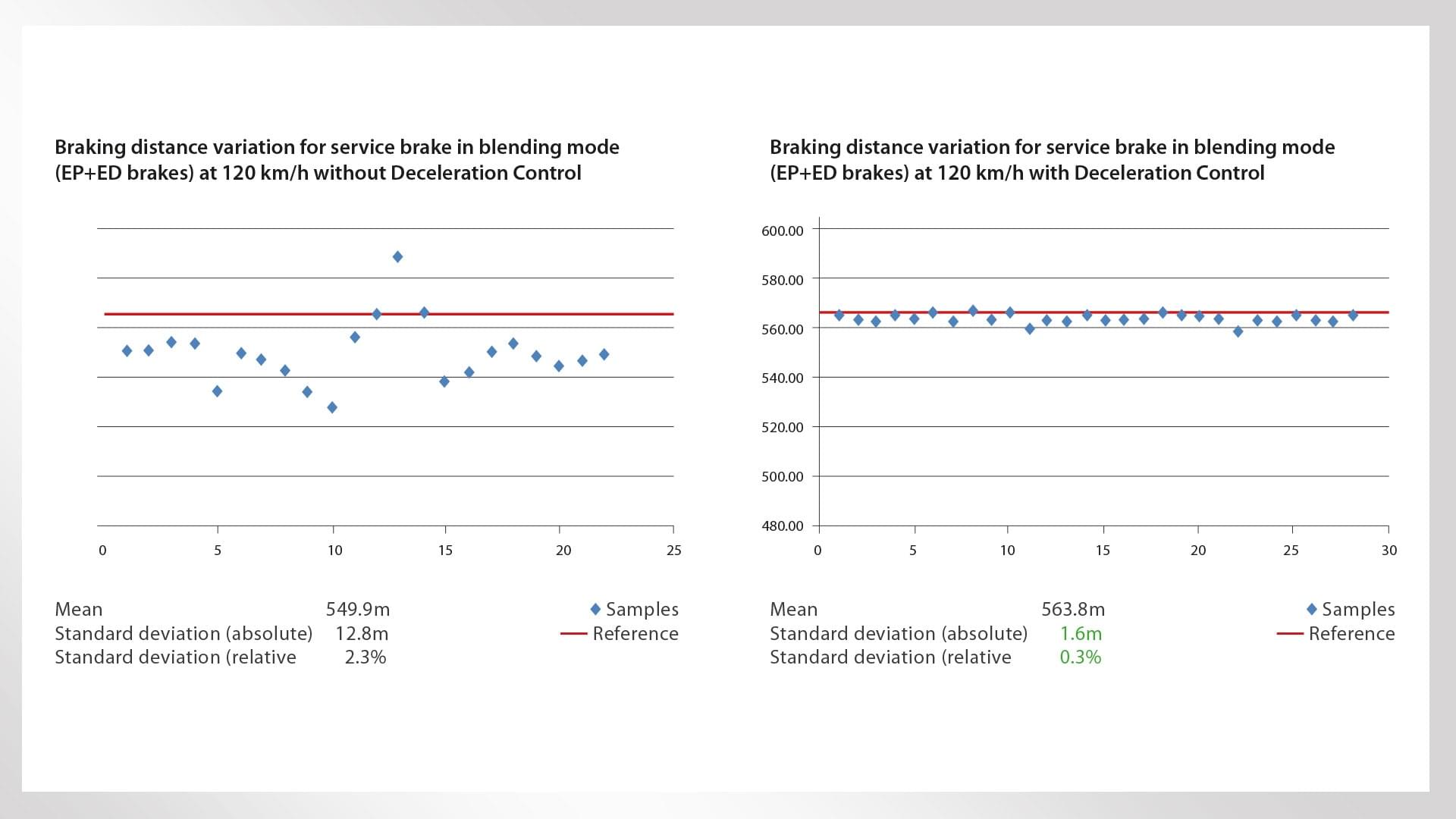
DCC’s efficiency was assessed using the standard deviation of the measurement series. For example, while the standard deviation from the average value for emergency braking from a speed of 120 km/h was 16.4 meters (3.6%) in “DCC off” mode, it was just 3.3 meters (0.7%) in “DCC on” mode. The measurements for different initial speeds and loads revealed similar differences between the two modes. Even in the case of combined electropneumatic and electrodynamic braking from the same initial speed, the standard deviation was 12.8 meters (2.3%) in “DCC off” mode and 1.6 meters (0.3%) in “DCC on” mode. This still equates to a reduction in braking distance variation of approximately 70% (Figures 8 and 9).
The measured values demonstrate that braking distance is also reliably reproducible in the case of emergency braking. The nominal/mean braking distance is set as a design parameter and can be adjusted slightly if necessary.
After the vehicle testing described above had been completed, it was time to begin the homologation process. This involved carrying out a series of test runs in line with the UIC/TSI standards. Once the evidence required by the Polish homologation authority Urząd Transportu Kolejowego (UTK) had been provided, in November 2019 the UTK approved the use of DCC on the NEWAG Impuls 36WEa. The next step will involve a one-year field trial on passenger service.
The lessons learned from the field trial with an Impuls 36WEa multiple unit equipped with active Deceleration Control will also underpin the deployment of DCC in the next generations of Knorr-Bremse braking systems. Deceleration Control and the sensors that it requires will be directly integrated into these new platforms, providing a valuable addition and enhancement to the braking systems’ functionality without the need for additional components or installation work.
Conclusion
The approval of the Impuls 36WEa multiple unit with DCC should be seen as an initial reference project that could potentially enable a far simpler verification procedure for the homologation process. With Deceleration Control, the train’s braking distance variation and adhesion utilization are significantly improved. The amount of work involved in carrying out future test runs should be substantially lower.
At present, the pneumatic brake is solely pressure-controlled and designed for a pre-specified brake pad type. Deceleration Control largely decouples braking distance variation from the tolerances of the braking system and bogie equipment. This means that, in the future, it will be possible to offer optimized friction material configurations, e.g. by finding brake pads that deliver the desired braking behavior while at the same time offering optimal wear behavior with low life cycle costs (LCC), enhanced thermal behavior or optimal noise reduction.
There are also potential value-added application scenarios in everything from Automatic Train Operation (ATO) to fully-fledged driverless systems or routes with platform screen door systems. By reducing braking distance variation, Deceleration Control offers significant benefits in scenarios where vehicles need to brake as precisely and as late as possible.
Authors: Ulf Friesen, Ralf Furtwängler, Norman Kreisel, Jörg Braeseke, Dariusz Ciesielski
Print Version
Deceleration Control