Just over four years ago, the launch of the KEf brake valve platform kicked off the wholesale replacement of the KE valve (KEdv) generation that had been in use ever since the mid-1950s. The next-generation platform offers new features that are more suitable for modern freight car operations – and lays the foundations for the Digital Freight Train, now one of the rail industry’s top priorities. An analysis of workshop findings provides a first evaluation of the new valves’ condition after several years of successful operation in the field.
80809 München
Deutschland - Germany
carina.smid@knorr-bremse.com

When the KE valve first came into regular use back in 1953, the engineering teams responsible for designing it essentially made railroad history. For the first time, the KEa distributor valve ensured that the brake cylinder was always filled and vented within the specified times, regardless of the brake cylinder’s actual size. But the KEa was just the start. Over the next few decades, some 500 KE valve variants were rolled out by development departments and rolled off production lines. First, because the valve positively called out for project-specific customization. And second, because technical advances inevitably resulted in regular improvements.
But the valve’s overwhelming advantage – that thanks to this adaptability, it was able to fulfil even the most exacting criteria required by hundreds of rail operators worldwide – was increasingly offset by two equally significant disadvantages. First, the proliferation of variants was steadily driving up maintenance costs due to the associated logistical and financial overheads. And second, the engineers were struggling to overcome an ever more challenging technical issue: how to fit all the latest advances into the narrow confines of installation spaces first defined back in the early 1950s. This is why, four years ago, the decision to switch over to the latest generation of brake valves was given the green light.
Summary
Just over four years ago, the launch of the KEf brake valve platform kicked off the wholesale replacement of the KE valve (KEdv) generation that had been in use ever since the mid-1950s. The next-generation platform offers new features that are more suitable for modern freight car operations – and lays the foundations for the Digital Freight Train, now one of the rail industry’s top priorities. An analysis of workshop findings provides a first evaluation of the new valves’ condition after several years of successful operation in the field.
Smart modular approach replaces some 500 different versions of the KE valve

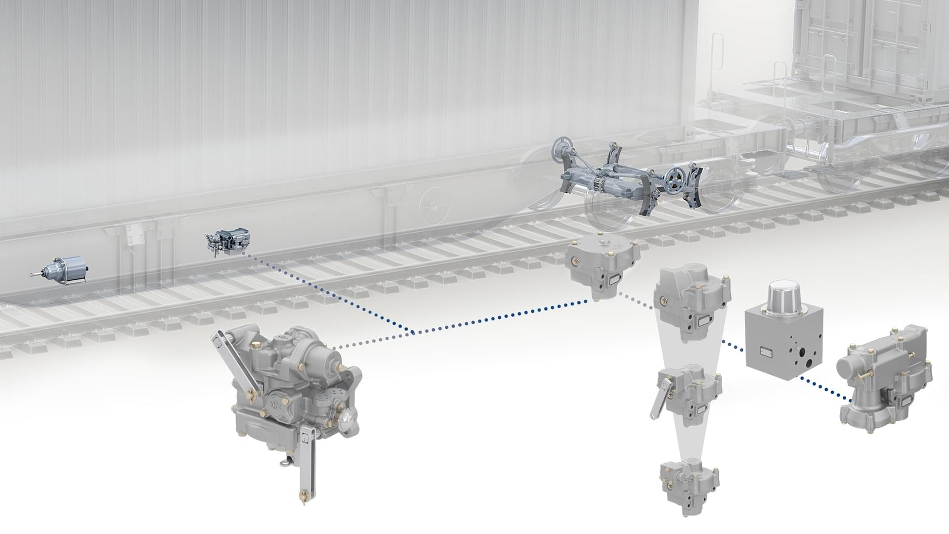
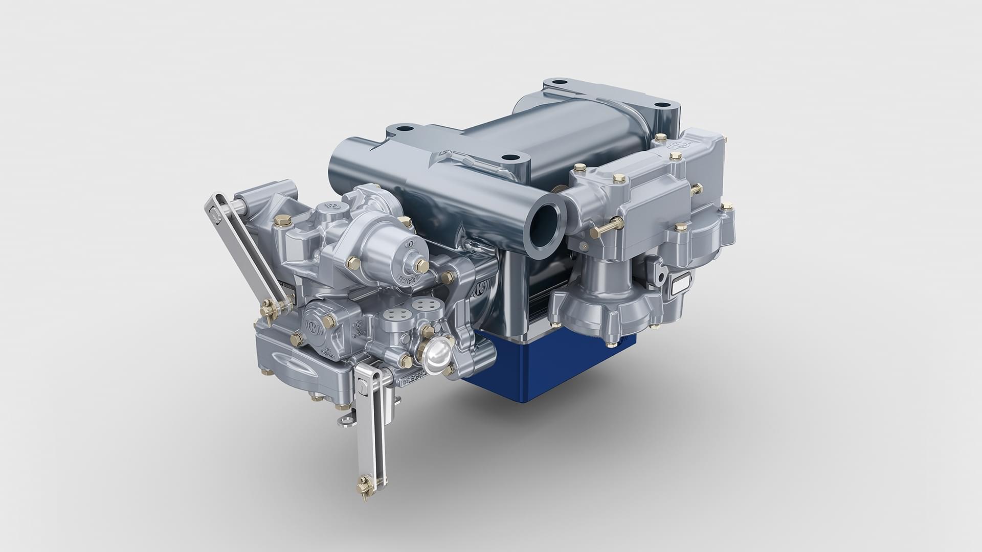
The new KE valve, which was developed from scratch, is complemented by a new modular system – also developed from scratch – consisting of one or two relay valves. This makes it possible to meet the specific requirements of various vehicle types in highly flexible ways, using a single distributor valve accompanied by a handful of KRf relay valves. The single-stage relay valves transform pilot pressure into brake cylinder pressure at a constant ratio. The two-stage relay valves provide two selectable ratios. The engineers also developed another, load-dependent KRf relay valve that operates at a continuously variable ratio.
It is precisely this flexible configurability that distinguishes the new valve generation from its predecessor. In the past, a more or less unique relay valve had to be designed and produced for every specification, each with its own part number – hence the enormous number of variants. Although the new range has been reduced from 500 to just 50 variants, the KEf family boasts an even larger range of adjustable settings for project-specific applications.
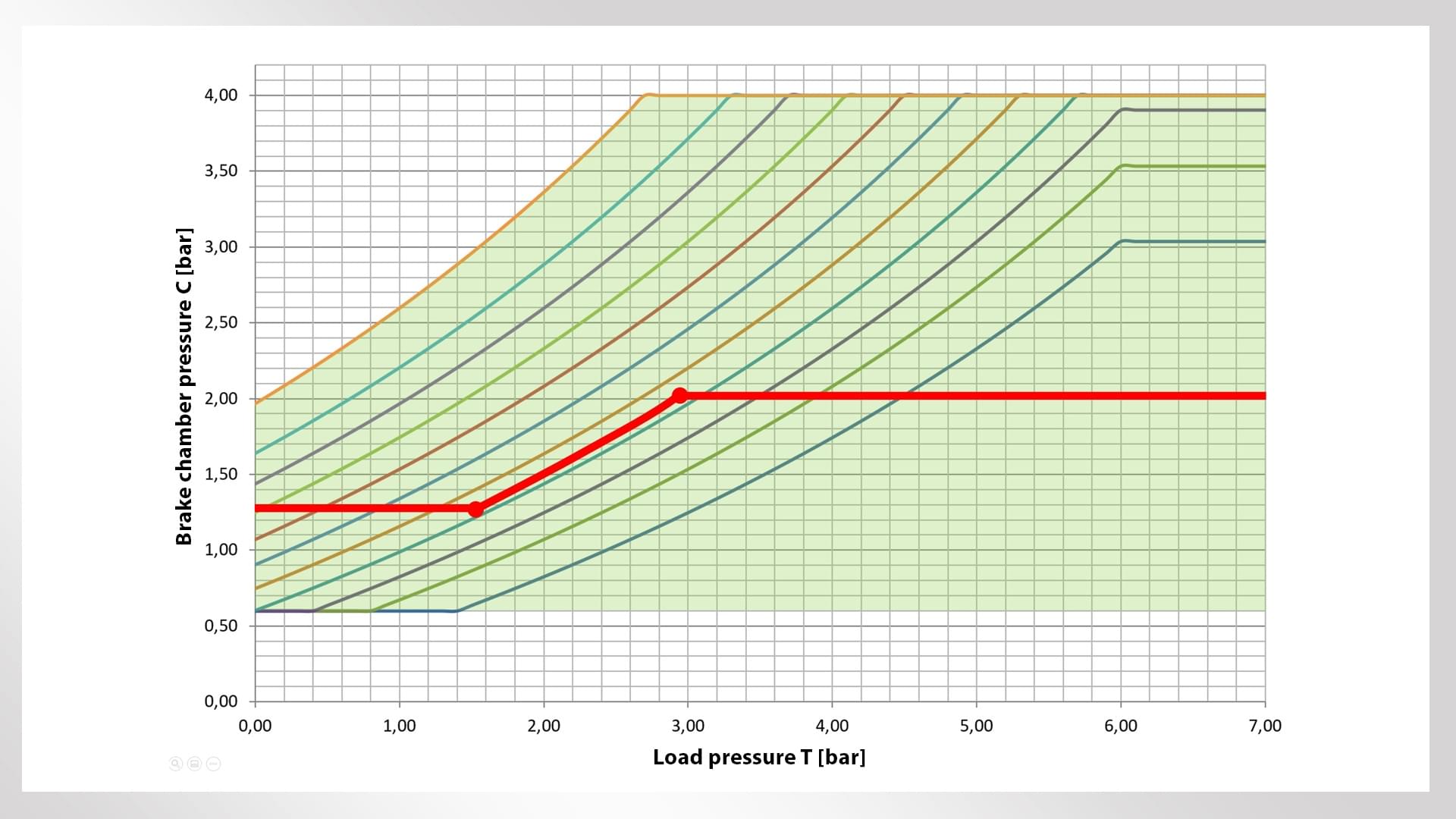
The modular KEf/KRf system focuses 90 percent of the characteristic curves typically achievable in the field into the 0.6-1.5 slope range. Despite (a very few) exceptions, the developers had good reasons for making this decision: It meant they could reduce the number of T springs to just ten without asking operators to accept restrictions on standard freight car characteristic maps. The new part numbers are now based on project-specific settings for characteristic maps; the settings are easy to adjust mechanically during the production process.

All the configurations required by customers are assembled from standard components and fitted with standardized interfaces. This approach has been carried over to the brake mechanism on the bogie, in the form of the TreadAct Freight compact brake unit (CFCB ). The production process for the new generation of valves also breaks new ground. Instead of the former complex, solid sand-cast design, the parts are now formed by drop-forging aluminum. When making this change, the developers were not just thinking about weight savings. Unlike sand casting, the new process does not require an additional cleaning stage for removing sand residue during production.
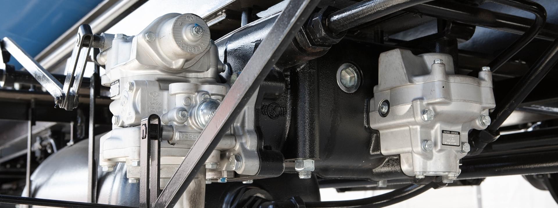
Whereas the only way to install the “old” KE valve in space-critical low-floor applications was to build a unique, dedicated solution for each application, the new KEf valve obviates this problem – even in its standard configuration. Among other things, this was achieved by mounting the distributor and relay valves separately in the carrier. Quite apart from the benefits of universal standardization, this has another not insignificant advantage in terms of maintenance and spare parts management. It is now easy to independently remove and replace the relatively small, lightweight distributor and relay valves. The carrier has no serviceable or replaceable parts, so simply stays on the vehicle while the valves are being serviced.
Just four years after they were first launched, the KEf and KRf valves are already regarded as firm fixtures in the European freight car market. Over 100,000 units (distributor and relay valves) are now in daily operation. The new valves are steadily replacing the previous generation. How long this will take is just a matter of time – more and more vehicle manufacturers and operators are already opting to equip their new vehicles with systems based on the KEf platform rather than a conventional “old” KE variant.
By the end of last year, for example, more than 3,000 KEf and KRf valves had been fitted to some 400 state-of-the-art T3000 pocket wagons built by Swiss rail car designer Ferriere Cattaneo. The company has been very impressed by the valves’ high availability levels. But the KEf’s compact design was also a key prerequisite for using the valves in the manufacturer’s very exacting, ultra-low T3000 configuration
Designed for rail freight digitization
There is plenty to suggest that the KEf family will have just as great an impact and ongoing influence on the history of rail freight as its predecessor. The valve is designed as a platform that should last for decades, not least because it is capable of supporting all the extended automation concepts currently under discussion by the Digital Freight Train developers involved in “Flagship Area 5” of the Europe’s Rail Joint Undertaking technology program. The interface for collecting pneumatic operating data, already an integral part of the system, is a key aspect of this support. The new data channel provides the essential prerequisites for applications ranging from condition-based monitoring – including continuous brake status monitoring by train drivers – through to automated brake testing for speeding up train preparation.
Impressive though such prospects are, by no means do they represent the proverbial end of the line. The KE family’s ability to integrate actuators opens the door to a whole raft of new functions and services in the future – such as, for example, a networked electropneumatic brake.
Authors: Thomas Petter, Jonas Heller, Steffen Jass
