
Development and validation of braking systems with the ATLAS wheel-rail adhesion test rig.
Generating reproducible braking distances has the potential to optimize the operational efficiency and utilization of the existing rail infrastructure. The aim is to leverage that potential through innovations in brake control. Knorr-Bremse’s Reproducible Braking Distance (RBD) concept is based on factoring wheel-rail adhesion and deceleration into the brake control system. Feasibility tests on the wheel-rail adhesion test rig demonstrated that, even under extremely unfavorable environmental conditions, this concept enables substantial benefits to be achieved in terms of braking distances, with no need to increase the installed braking power. The test rig proved its worth here as a development and validation tool, operating under conditions which, in view of the cost, effort and risk involved, could only be implemented with difficulty in field tests. In the process, tests with original braking and running gear are combined with mathematical simulation of rail vehicles and with databases containing field test data.
Contact
Carina Smid Marketing Rail
80809 München
Deutschland - Germany
carina.smid@knorr-bremse.com
Factoring the wheel-rail contact into the brake control system
Conventional compressed air brake control systems regulate bogie brake cylinder pressure in line with brake demand and vehicle load information. The wheel slide protection system keeps wheel slip within the specified limits. However, braking/stopping distances are also influenced by (pressure control circuit and coefficient of friction) tolerances and by disturbance variables (environmental factors such as weather effects and track contamination) that are not input into the brake control system’s control circuit. In principle, the same problems also apply to electrodynamic braking.
A large-scale simulation study carried out in cooperation with Berlin’s Institut für Bahntechnik as part of the EU’s Shift2Rail program found that improved braking distance reproducibility has the potential to optimize rail infrastructure utilization, in some cases to a significant degree [1] (RBD). The theoretical headway reductions on a dry track were found to be in the following ranges: metros: 9% – 19%, S-Bahn trains: 9% – 16%, regional multiple units: 1.5% – 4%, and high-speed trains: up to 20%. The ranges for wet tracks were as follows: metros: 10% – 13%, S-Bahn trains: 10% – 12%, regional multiple units: 4% – 7%, high-speed trains: up to 20%. The variations in the theoretical headways are due to the different operating and line parameters and the difference between fixed blocks (Level 2) and moving blocks (Level 3) in the ETCS train control system.
Rather than allowing vehicles to brake harder, the aim of the integrated new deceleration control, wheel slide protection (WSP) and adhesion management systems is to increase the Emergency Brake Confidence Level by reducing braking distance variation. This makes it possible to reduce the headway between trains without compromising on safety.
Adhesion management plays an especially important role, since no other technology can deliver a sufficient improvement in (momentarily) extremely poor wheel-rail adhesion, especially with disc brakes. However, the development of adhesion management solutions for braking systems is complicated by the need to prepare entire track sections for the appropriate field tests. This makes the tests time-consuming, hazardous or even impossible
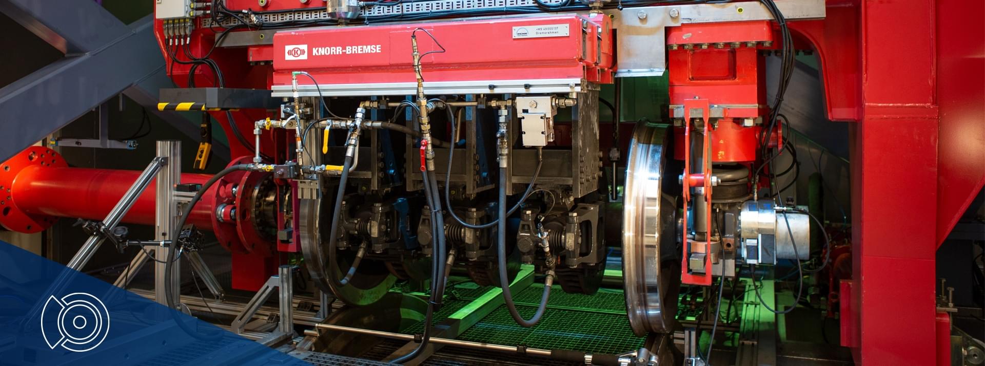
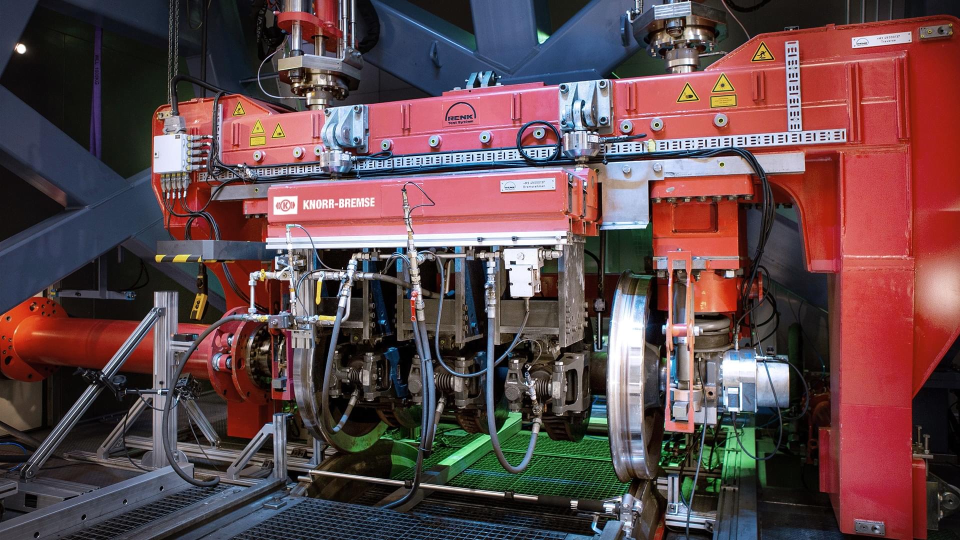
Consequently, test rigs such as Knorr-Bremse’s wheel-rail adhesion test rig ATLAS (Advanced Test Laboratory for Adhesion-based Systems) (Figure 1) play an extremely important role in the development and validation of first-time-right prototypes. ATLAS enables testing with original equipment at speeds of up to 350 km/h, under a wide range of reliably reproducible environmental conditions. The test-rig testing follows a V-shaped development model. Basic testing is followed by feasibility studies that are still decoupled from specific computer hardware. Finally, tests are carried out with product prototypes. This ensures that there is already a high degree of confidence when the first field test begins.
Summary
Generating reproducible braking distances has the potential to optimize the operational efficiency and utilization of the existing rail infrastructure. The aim is to leverage that potential through innovations in brake control. Knorr-Bremse’s Reproducible Braking Distance (RBD) concept is based on factoring wheel-rail adhesion and deceleration into the brake control system. Feasibility tests on the wheel-rail adhesion test rig demonstrated that, even under extremely unfavorable environmental conditions, this concept enables substantial benefits to be achieved in terms of braking distances, with no need to increase the installed braking power. The test rig proved its worth here as a development and validation tool, operating under conditions which, in view of the cost, effort and risk involved, could only be implemented with difficulty in the real world. In the process, tests with original braking and running gear are combined with mathematical simulation of rail vehicles and with databases containing field test data.
Use cases and test conditions
Test series begin with tests designed to obtain basic data about factors such as the effect of wheel slip and how different types of wheel and rail contamination affect adhesion. Other use cases include feasibility testing and potential analysis of algorithms for innovative brake control techniques, preliminary validation of technical solutions prior to the first in-vehicle tests, and testing of settings and braking distances for specific projects.
Since the material properties of the wheel, rail and interlayer are not scalable, the original dimension and force values are important for all types of testing. This explains why original braking equipment is used. The vehicle’s kinetic energy is simulated by a 1.4 MW drive. Expert reports and calculations have demonstrated that the test rig results accurately reflect field test results, and regular checks are carried out to reaffirm this. The results cover parameters such as braking distance, wheel slip, coefficient of friction, wheel-rail adhesion and temperature.
The test rig is fully housed in a climate chamber where it is possible to generate precisely reproducible headwind, rain, atmospheric humidity, heat and cold under laboratory conditions. Added realism is provided by rail surface contamination that can simulate dew, fog, drizzle, heavy rain, soap solution, oil and even compacted black leaf layer.
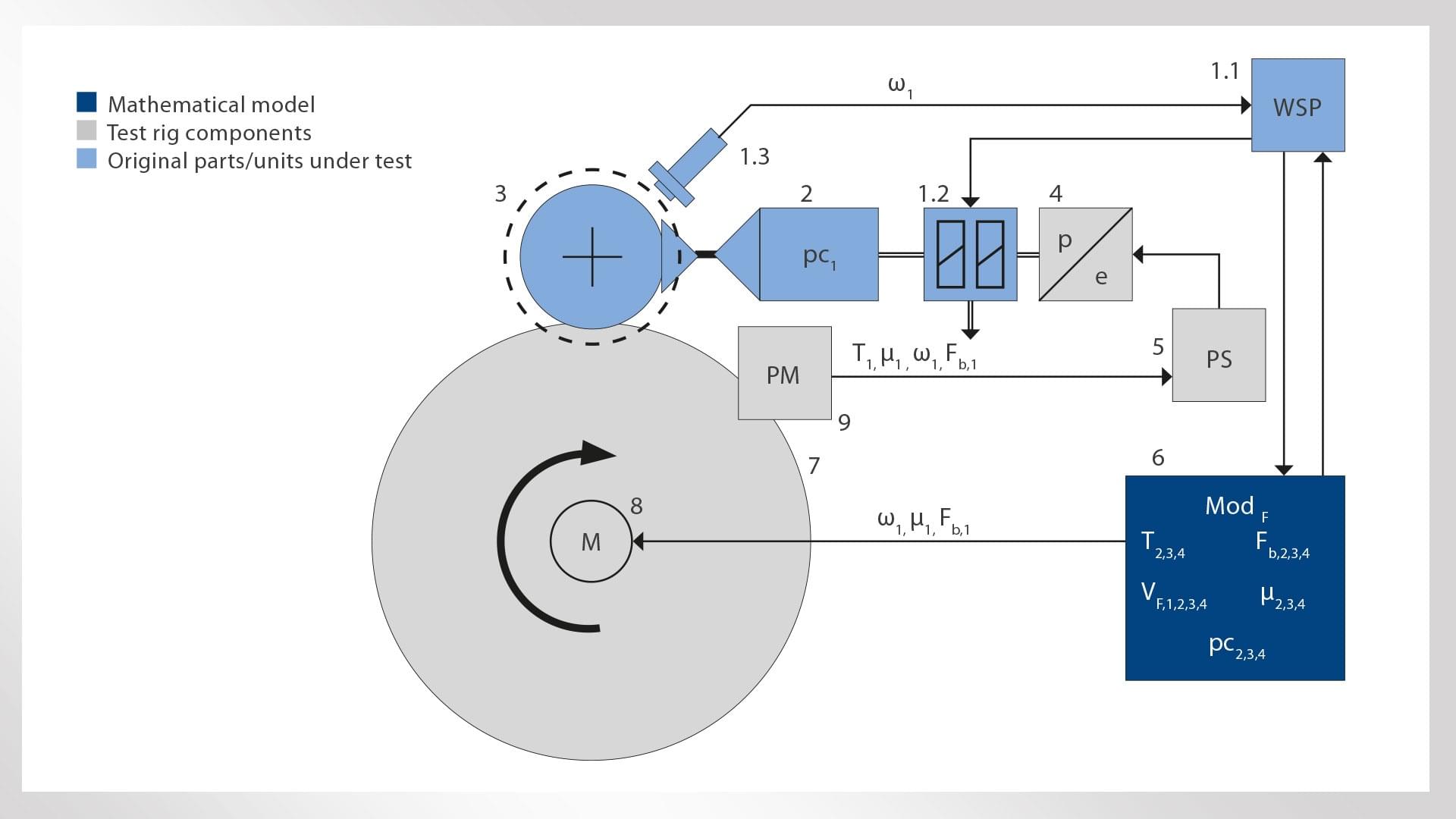
Since vehicle braking is usually determined by the combined effect of at least four wheelsets, the real wheelset is incorporated into a simulation calculation of an entire train/vehicle (Figure 2). Led by the measurements of the real lead axle, the calculation also incorporates additional field test data, for example on how adhesion changes from one wheelset to the next. A wheel slide protection system regulates wheelset brake cylinder pressure, making no distinction between actual wheelset hardware on the test rig and virtual components of the simulation calculation.
Selected deceleration control system test results
Rail vehicle braking distances are calculated by double integration of deceleration. The more precisely deceleration is controlled, the more accurately the braking distance can be determined. The deceleration control system (DCC) can also directly achieve limited adhesion utilization, one of the other aims of the brake control system. For example, wheel-rail adhesion utilization of 15% equates to a deceleration of 15% of acceleration due to gravity, or approximately 1,5 m/s². The deceleration control system compensates for variability in the brake pads’ momentary coefficient of friction and, within certain limits, for variability resulting from aquaplaning, snow and ice.
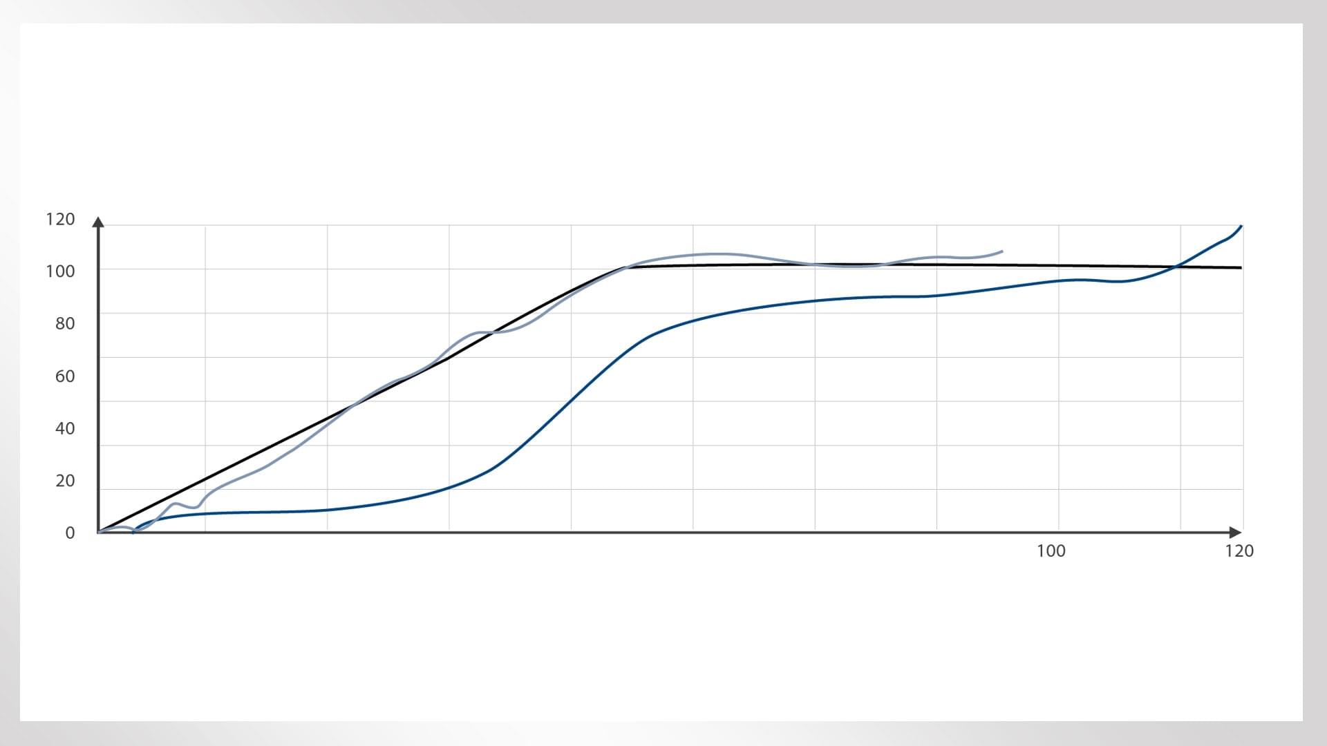
Figure 3 illustrates the principle and benefits of deceleration control by comparing pressure-controlled braking against braking using the deceleration control system on a dry track. In a test run with a constant brake cylinder pressure, deceleration varies in line with the changes in the brake pad coefficient of friction that occur during braking. The coefficient of friction is at its highest shortly before the vehicle comes to a halt. In practice, this causes an unwanted jolt when the vehicle stops, detracting from passenger comfort and increasing the danger of the wheels locking. On multiple units, the brake control system often tries to compensate for the service brake jolt. An experienced multiple unit driver can also compensate for it with a release stage.
When braking is carried out using the deceleration control system, the characteristic bump in the deceleration curve is leveled out, eliminating the jolt when the vehicle comes to a halt and decoupling braking distance from limited variability in the brake pad coefficient of friction.
One extreme scenario investigated during basic testing (Figure 4) involved inducing brake disc aquaplaning. This can occur briefly during heavy rain, when water is whirled up under the train. The deceleration control system instantly detects the aquaplaning and compensates for it within a fraction of a second by boosting the brake cylinder pressure. Without deceleration control, several seconds may elapse before the water is displaced from the brake pads.
Extremely low adhesion conditions – the black leaf layer problem
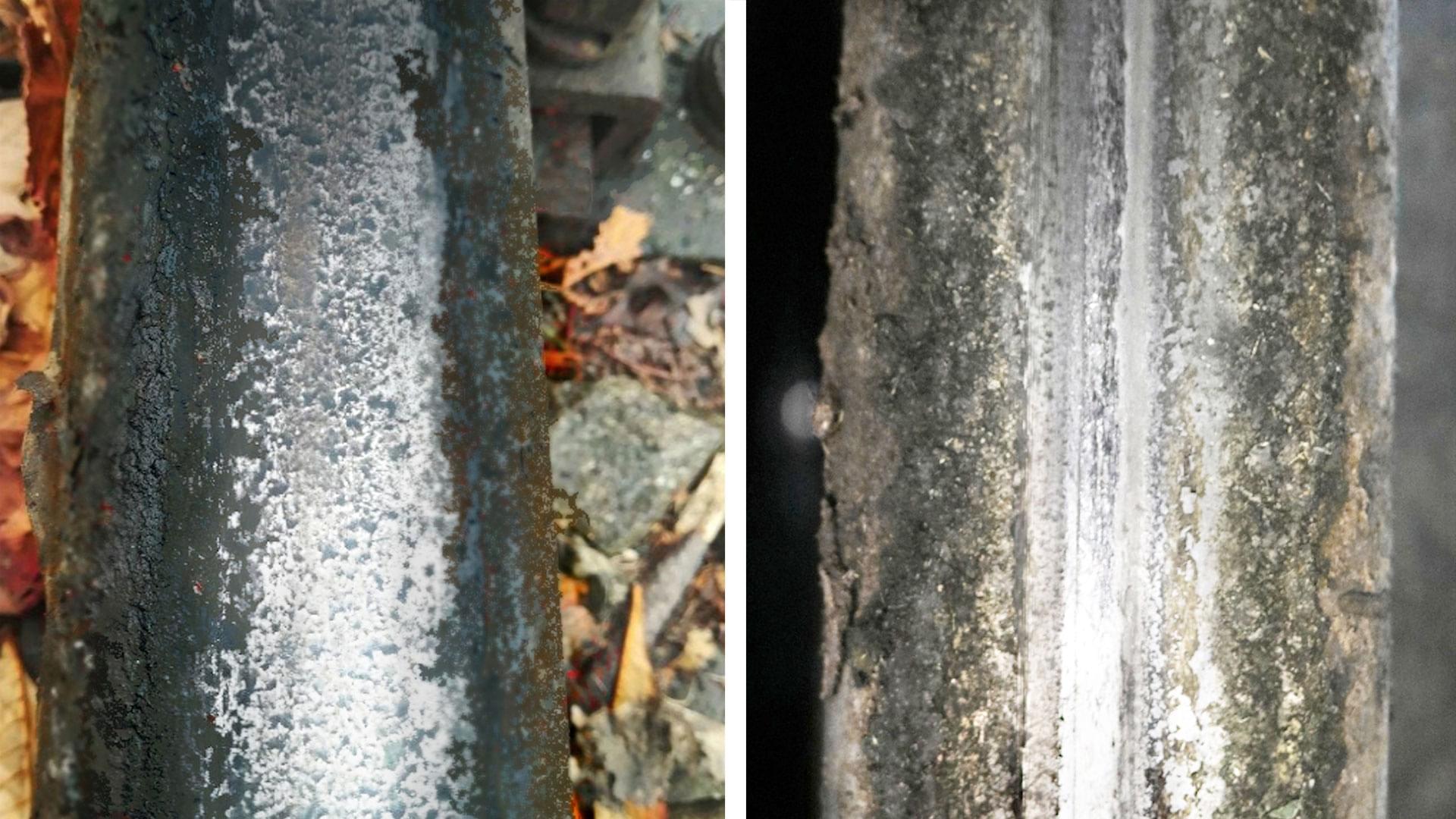
The wheel slide protection system can compensate for “normal” adverse adhesion conditions. Innovative solutions enable adhesion to be improved by driving within an optimal slip range. In practice, however, phenomena such as a wet, compacted black leaf layer (Figure 5) can sometimes cause extremely adverse conditions on the rails.
These conditions were replicated on the wheel-rail adhesion test rig using a custom technique and special equipment. A black leaf layer can withstand being driven over several times, especially in fog or light drizzle. In the absence of adequate sanding, it reduces wheel-rail adhesion to just 20% of the required value.
Although the wheel slide protection system still prevents the wheels from locking even under these conditions, the laws of physics make it difficult to bring the train to a halt within specified braking distances. By detecting which slip range provides optimal braking force transmission, innovative wheel slide protection systems can ensure that the maximum achievable force is transmitted [2].
Rationale for new adhesion management system and results
The original, tried-and-tested form of adhesion management involves driver-activated sanding using compressed air or electromechanical sanding units with controllable sand output. An experienced driver who anticipates the condition of the track ahead can achieve good results on trains equipped with a sufficient number of operational sanding units.
However, automatic sanding that is activated without delay as and when required is not only an attractive solution for automatic traction and brake control scenarios, since it can significantly increase braking distance reproducibility. The braking distance of a train traveling at 50 m/s (180 km/h) is almost 150 m longer if sanding is activated manually with a three-second delay. Moreover, the sand output required to achieve the necessary adhesion is at least five times greater at 50 m/s than at 10 m/s. Use too little sand, and the impact on braking distance is diminished. Use too much, and insulating layers form on the track. This can disrupt track release signaling and cause unnecessary track bed contamination.
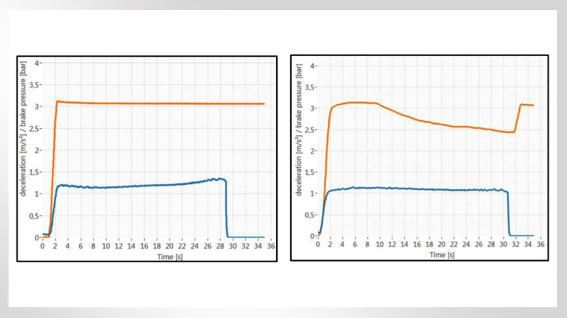
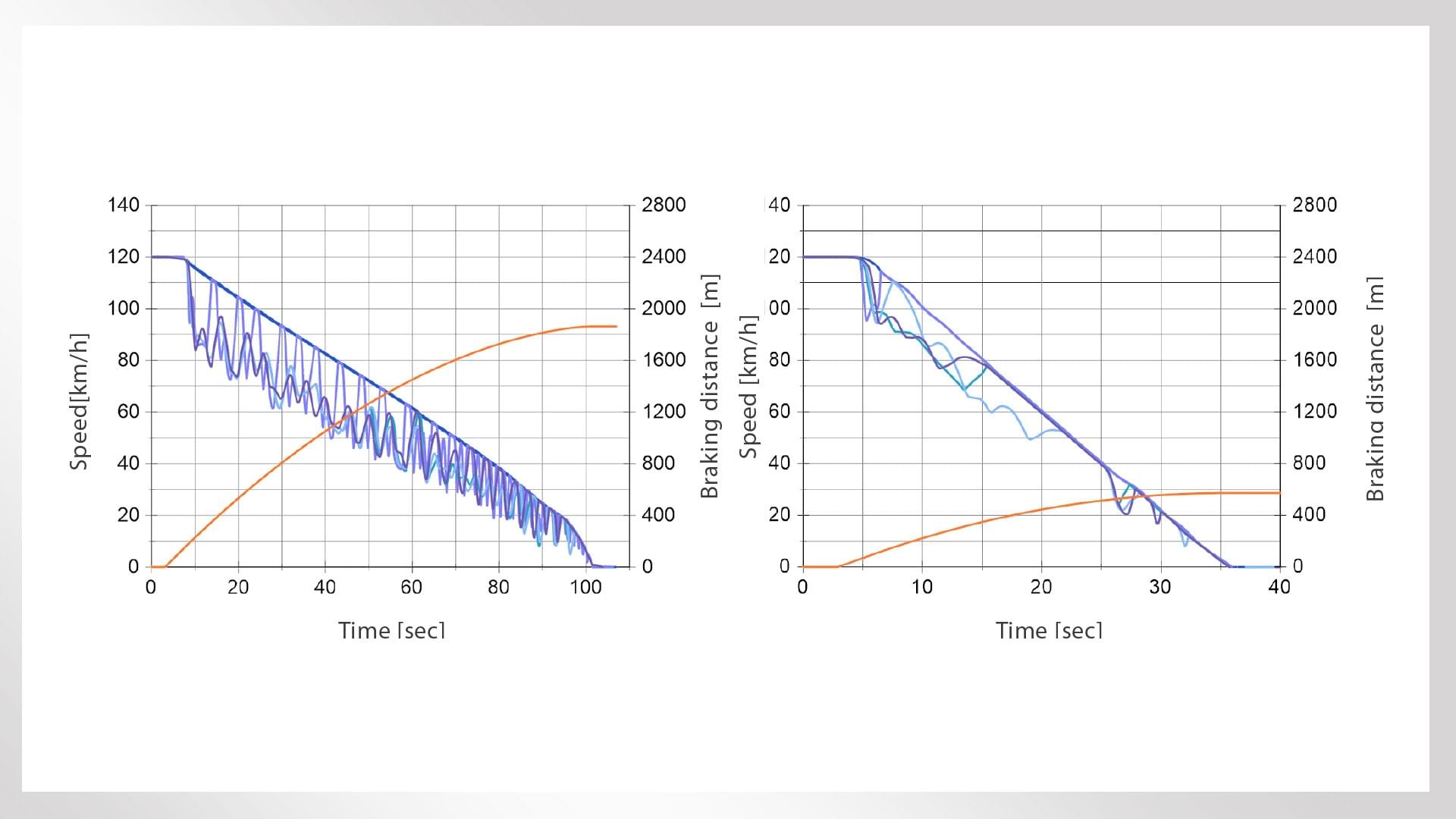
Data recorded on the wheel-rail adhesion test rig shows how an automatic system is able to meet these complex requirements (Figure 6). The system evaluates the adhesion of all the wheelsets in real time and, if necessary, delivers exactly the right amount of sand to compensate for the loss of adhesion at the current speed, in just a fraction of a second.
Without automatic sanding (left-hand graph in Figure 6), the wheel slide protection system keeps all the wheelsets within the desired macroslip range. However, this requires brake cylinder pressure to be significantly reduced, meaning that it is no longer possible to bring the vehicle to a halt within the required braking distance. In this example, the actual braking distance is almost two kilometers instead of the projected figure of 529 m.
When an automatic sanding unit is used to sand the first of four wheelsets (right-hand graph in Figure 6), macroslip is eliminated on the first two wheelsets within a few seconds, while the other two wheelsets stabilize within an optimal range.
Other areas of application for the wheel-rail adhesion test rig
The wheel-rail adhesion test rig’s main areas of application are by definition the optimization of wheel-rail adhesion and the wheel slide protection system. However, it can also be used for several other types of testing that are also extremely important for the development of advanced rail technology. These include tests relating to the noise caused by rail vehicles, the interaction between brake blocks and wheels, the alternating thermal and mechanical stress at the contact patch during braking, the behavior of brake force actuators in relation to wheelset motion during operation, and the effect of track brakes and cleaning blocks.
Authors: Martin Heller, Jörg Koch, Christian Burger, Andreas Festel
References:
[1] Englbrecht, Linke, Hohmann, Gremmel. Höhere Transportkapazitäten auf der Schiene: Simulation zeigt Potenziale für optimierte Auslastung bestehender Infrastruktur. ZEVRail, 08/2020
[2] Meyer, Rasel. Höhere Zugtaktung: Neuartiger Gleitschutz für eine verbesserte Auslastung der Schieneninfrastruktur. ZEVRail, 11-12/2020
Download / Print Version
ATLAS